Author Topic: testing the egs002 inverter board  (Read 152328 times)

0 Members and 2 Guests are viewing this topic.

Offline Madness

  • Newbie
  • *
  • Posts: 13
  • Karma: +0/-0
Re: testing the egs002 inverter board
« Reply #555 on: February 15, 2018, 04:32:21 am »
I have had very good results from this supplier. https://www.aliexpress.com/store/2383059

Offline tinyt

  • Newbie
  • *
  • Posts: 18
  • Karma: +0/-0
Re: testing the egs002 inverter board
« Reply #556 on: February 17, 2018, 08:59:39 am »
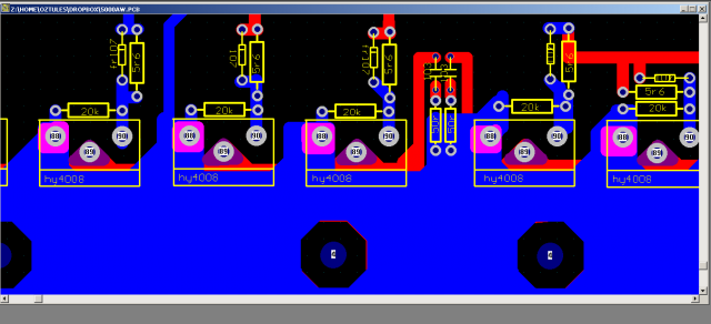
Have started an ozinverter build thread at the back shed and I would like to share here the schematic I made. I hope I did not make mistakes. And sorry for the 'side trip'.

Offline Phaedrus

  • Jr. Member
  • **
  • Posts: 28
  • Karma: +0/-0
Re: testing the egs002 inverter board
« Reply #557 on: February 18, 2018, 11:53:21 pm »
Hi TinyT,
Thanks for posting the schematic.
Any major changes from the one you posted on Reply #506 ?
My inverter works erratically,sometimes it works like a charm and sometimes it blows MOSFETs  :-[.
I am using a DC-DC buck converter for the 15V conversion. Time to build a "pure" Oztules ,I think.

Offline Phaedrus

  • Jr. Member
  • **
  • Posts: 28
  • Karma: +0/-0
Re: testing the egs002 inverter board
« Reply #558 on: February 19, 2018, 12:14:02 am »
Hi again,
These are the latest CAM files AFAIK.Is it OK to go ahead and make these ?

Offline tinyt

  • Newbie
  • *
  • Posts: 18
  • Karma: +0/-0
Re: testing the egs002 inverter board
« Reply #559 on: February 19, 2018, 06:51:17 am »
Hi TinyT,
Thanks for posting the schematic.
Any major changes from the one you posted on Reply #506 ?
....
In the control PCB, the only change I made is identify the signal names at the pins of the ribbon connector J8.
The schematics I made came from the gerber zip files you posted. But I don't know if there are anymore revisions in the gerber files.

Offline Phaedrus

  • Jr. Member
  • **
  • Posts: 28
  • Karma: +0/-0
Re: testing the egs002 inverter board
« Reply #560 on: February 19, 2018, 01:12:19 pm »
Hi TinyT,
Thanks for posting the schematics.
I think some minor differences in component values in the Power Board.The snubber capacitors viz. C1,C2,C9,C8 should be 472,250V and resistors R5,R6,R23,R24 should be 5E6.
Also there are 2 safety capacitors on the edge of the board,are not mentioned in the schematic.Kindly refer the pic in post #532,and replies from Oztules and ClockmanFrance in #533,#534.Hopefully the experts here will correct me if I am mistaken.

Offline tinyt

  • Newbie
  • *
  • Posts: 18
  • Karma: +0/-0
Re: testing the egs002 inverter board
« Reply #561 on: February 19, 2018, 04:15:19 pm »
Hi Phaedrus,

Attached are the silkscreen and top copper gerbers from where the schematic came from, it says 'oztules 5kw power board'. See also post # 539.

The snubber capacitors C1,C2,C8,C9 are silkscreened as 103 and the resistors R5,R6,R23,R24 are silkscreened 50r, I can correct my 56r to 50r when I have time. There are no capacitors at the two corners.

I think there are two designs, the pictures in post #532, #534 are probably for a bigger power board, note that in those pictures, there are 6 large 10000 uF capacitors instead of 4.The blue capacitors at the two corners are probably bypass capacitors to chassis as they appear to be connected to the mounting hole pads.

Just my observations.

Offline oztules

  • Moderator
  • Hero Member
  • *****
  • Posts: 1177
  • Karma: +105/-8
  • Village idiot
Re: testing the egs002 inverter board
« Reply #562 on: February 20, 2018, 04:42:29 am »
This may help.
7441-0

The units work out of the box, and there are many here now. They are solid as all get out, and folks give them a real beating..... they don't die.
Many folks seem to make changes, and they suffer for it. As built, they are seemingly bullet proof.
Tiny, 56r will over heat and kill the fets in my experience.... 5r6 is fine.

Been busy, and didn't notice this thread was alive.

will take any questions you may have.

Oh, and I use an 18v zener instead of the 13v zener, and that may help with gate drive voltage. Check your turn on voltages, they may be a bit low perhaps. other than that I can;t see any difference. I used that gerber for the last boards I got done.

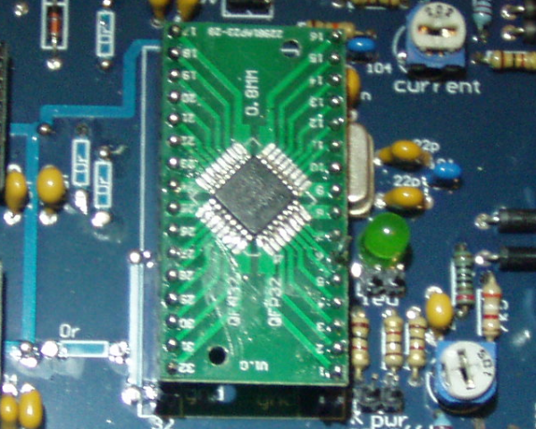
What is not shown on the boards, is that the 8010 has pin 6 raised out of the board, and is used for on/off. The pin does not go to the control board, but is isolated from it as it sticks up not down, and the pin is used to go to the 5v or ground for on / off. If left floating it will go on/off erratically... not good, but generally does not kill anything either, just unstable.

Remember too, if you use a starting resistor to get the caps charged, you will have to reset the chip. or it will hang dead. I reset by shorting the 120r after the resistor to ground with a push button... rough, but works just fine.

You may just see the pin 6 sticking up here.

Also check you have not got any dry joints with soldering the 8010 on the daughter board
7443-1


.........oztules

Flinders Island...... Australia

Offline tinyt

  • Newbie
  • *
  • Posts: 18
  • Karma: +0/-0
Re: testing the egs002 inverter board
« Reply #563 on: February 20, 2018, 09:15:52 am »
Hi oztules,

Thanks for the updates. How about the snubber caps C1,C2, C8, and C9 are they still 103 or now changed?

Offline oztules

  • Moderator
  • Hero Member
  • *****
  • Posts: 1177
  • Karma: +105/-8
  • Village idiot
Re: testing the egs002 inverter board
« Reply #564 on: February 20, 2018, 04:38:43 pm »
snubbers I use 3kv 103.
I had 1000 18v zeners, so I tend to use them everywhere.


........oztules
Flinders Island...... Australia

Offline Dr_Zogg

  • Full Member
  • ***
  • Posts: 109
  • Karma: +0/-0
Re: testing the egs002 inverter board
« Reply #565 on: February 21, 2018, 03:22:44 am »
thanks for the help everyone.,
with the 103 caps on the power board what type are they?

I also have a couple of spare control power and fan control boards made from the gerbers in this thread if anybody is in need of them without having to get more than one made.


Cheers,
           Sam
Of all the things I've lost, I miss my mind the most

Offline oztules

  • Moderator
  • Hero Member
  • *****
  • Posts: 1177
  • Karma: +105/-8
  • Village idiot
Flinders Island...... Australia

Offline Dr_Zogg

  • Full Member
  • ***
  • Posts: 109
  • Karma: +0/-0
Re: testing the egs002 inverter board
« Reply #567 on: March 05, 2018, 04:01:44 am »
another quick question. is it ok substitute the 50r resistors on the power board for 51r or 56r? it is just that they are a common value that i keep on hand

Thanks,
           Sam
Of all the things I've lost, I miss my mind the most

Offline Phaedrus

  • Jr. Member
  • **
  • Posts: 28
  • Karma: +0/-0
Re: testing the egs002 inverter board
« Reply #568 on: March 05, 2018, 05:23:47 am »
Quote
another quick question. is it ok substitute the 50r resistors on the power board for 51r or 56r? it is just that they are a common value that i keep on hand
I think the value to be used is about 5.6 ohms,not 56 ohms.

Offline Phaedrus

  • Jr. Member
  • **
  • Posts: 28
  • Karma: +0/-0
Re: testing the egs002 inverter board
« Reply #569 on: March 05, 2018, 11:45:41 am »
Sorry to create confusion,but maybe Oztules can clarify once and for all :
1) Gate drive resistors : 5r6 aka 5.6Ohms
2) Snubber resistors    : 5r6 aka 5.6Ohms (Metal Oxide 1W)
3) Snubber Capacitors : 103 ,3kV