Author Topic: Electric Fence Zapper  (Read 117138 times)

0 Members and 5 Guests are viewing this topic.

Offline oztules

  • Forum Advisors
  • Hero Member
  • ****
  • Posts: 1177
  • Karma: +105/-8
  • Village idiot
Re: Electric Fence Zapper
« Reply #240 on: October 12, 2015, 07:25:51 am »
The little transformer on the dc fencer needs to be ferrite, not iron..... as an output one it would die yes... you would have to have a lot more current drawn to run it as an inverter style transformer. I use etd49 ferrites ones. for the step up.

The trippler 110vac circuit is where the 3 x 150v came from.. did not understand you wanted to go DC.

.........oztules
Flinders Island...... Australia

Offline dalek

  • Newbie
  • *
  • Posts: 13
  • Karma: +1/-0
Re: Electric Fence Zapper
« Reply #241 on: October 12, 2015, 07:57:18 am »
The little transformer on the dc fencer needs to be ferrite, not iron..... as an output one it would die yes... you would have to have a lot more current drawn to run it as an inverter style transformer. I use etd49 ferrites ones. for the step up.

The trippler 110vac circuit is where the 3 x 150v came from.. did not understand you wanted to go DC.

.........oztules

So I'll have to find some other project to use those little Radio Shack type transformers for?   Great.  LOL 

Yea, this one I am keeping small and not so high a voltage except in the end at the output.  Hopefully it will be a little cheaper to build and last a little longer to given the lower voltages and such.  Sort of anyway.   Maybe not. 

I tried to open that file trippler.PCB and for some reason, it doesn't load up anything.  Maybe I have a wrong version of software here or something.  As I said before, I'm a Linux user.  I'm not sure what anyone else uses here.  I may try to get this done here if I can figure out how to make one of these programs work and whoever makes the boards can use it.  Otherwise, I'm hoping someone else will help out either making them or sending me files that I can use to get them made. 

Offline oztules

  • Forum Advisors
  • Hero Member
  • ****
  • Posts: 1177
  • Karma: +105/-8
  • Village idiot
Re: Electric Fence Zapper
« Reply #242 on: October 12, 2015, 12:38:59 pm »
http://getintopc.com/softwares/simulators/protel-99-se-free-download/ will get you a windows program.. it is big ..118mb

 I use protel for windows  (PFW) generally under wine.... but have not seen a download for it. 99se was it's big brother back in the day.

The company is now called altium..

Board manufacturers around the world use it... america is a bit different though.


...............oztules
Flinders Island...... Australia

Offline dalek

  • Newbie
  • *
  • Posts: 13
  • Karma: +1/-0
Re: Electric Fence Zapper
« Reply #243 on: October 17, 2015, 04:32:34 pm »
Oztules,

I been ordering some components to build this fence charger and studying the schematic a bit too.  I'm uncertain about something tho.  What I read in the text and what I see in some of the pics of what people have built seems to differ.  On the high voltage side of this, or the right side of the schematic, is where my question is.  On the schematic it shows a inductor between the output transformer, microwave transformer for you, and the bank of triacs.  Is that a part of the transformer or a separate inductor to help reduce feedback spikes or some other perpose?  Based on a pic posted here and the diodes placement in the schematic, I'm pretty sure it is a separate inductor but I want to be sure.

Also, David was kind enough to send me the files for the circuit and PCB.  Thing is, I'm Linux only with not even a remote possibility of putting windoze on here.  I may have to go to plan B.  I may see if I can get David to order the PCBs from a China maker and me paying for it.  Ross mentioned that he found one that may can do 20 or so for around $40.  For the trouble, I'd be willing to print a few extras and David keep them.  Anyway, I'm still trying to figure out some easier way but may have to talk to David about this.  I'd prefer them be done by a pro since I haven't made a PCB in ages. 

Rossw,

if you have a link to that Chinese maker you found, I'd love to check into it.  I'd like to see exactly what they need to make them. 

Thanks to both. 

Offline rossw

  • Senior Moderator
  • Hero Member
  • *******
  • Posts: 879
  • Karma: +35/-0
  • Grumpy-old-Unix-Admin
Re: Electric Fence Zapper
« Reply #244 on: October 17, 2015, 04:42:17 pm »
Rossw,

if you have a link to that Chinese maker you found, I'd love to check into it.  I'd like to see exactly what they need to make them. 

I'm out on the mower at the moment and shearing this afternoon.
There are any number of them out there competing for your business. All the ones I've used simply  need gerbers for each layer (component side copper, solder side copper, optionally component and solder side solder masks, silk screens. At least one layer must have board layout and any cutouts. And a drill file.

Offline oztules

  • Forum Advisors
  • Hero Member
  • ****
  • Posts: 1177
  • Karma: +105/-8
  • Village idiot
Re: Electric Fence Zapper
« Reply #245 on: October 17, 2015, 07:30:19 pm »
The inductor is separate to the transformer.
The pcb is protel, any chinese pcb maker will take just that file, and do the rest.

The inductor is for wave shaping.

A good transformer is key to making the thing powerful.

I only use linux also. Wine will run most things windows though

................oztules
Flinders Island...... Australia

Offline dalek

  • Newbie
  • *
  • Posts: 13
  • Karma: +1/-0
Re: Electric Fence Zapper
« Reply #246 on: October 20, 2015, 12:51:49 am »
Thanks oztules.  I was thinking it was because of the pictures others posted but wanted to be certain.  I didn't want to build this thing and it be wrong and not work. 

Based on your previous posts, that transformer is what sets your circuit apart from what we can go buy in a store.  Those always have small transformers, that I have seen anyway.  They "claim" to have power but maybe there is a little trickery there.  ;)

I have Eagle CAD installed, along with several other programs that do PCBs and such and am making progress on putting it in.  I started putting it in and then went digging for a video howto.  After watching a little of the video, wrong, doing it all wrong.  Eagle was telling me something wasn't right which is why I went digging.  I'll start over and learn some more.  This is the first time I did one on a puter.  I usually use a pencil to draw it out and then do the layout by hand on the PCB using those dry transfer etch resist things that Radio Shack sells.  A whole new experience for me. 

Offline oztules

  • Forum Advisors
  • Hero Member
  • ****
  • Posts: 1177
  • Karma: +105/-8
  • Village idiot
Re: Electric Fence Zapper
« Reply #247 on: October 20, 2015, 01:47:06 am »
This is the 12v version I use now...
print onto A4 plain paper, coat with olive oil, place on Kinsten pos pcb board. expose to desk fluro for 30 mins@ 100mm distance
use lye to develop, and then etch.
 Too simple.

The little transformer is the tricky thing. The coils must be the right way around for it to oscillate.... thats why the tracks don't connect... test and then connect accordingly.

....oztules
Flinders Island...... Australia

Offline David HK

  • Sr. Member
  • ****
  • Posts: 250
  • Karma: +21/-0
  • No Personal Text Set by User
Re: Electric Fence Zapper
« Reply #248 on: October 20, 2015, 01:53:46 am »
Dalek,

What copper thickness do you want? The Express PCB website Help section shows this specification: 

Our laminate is 0.062" FR-4 epoxy glass with 1/2 ounce copper. We plate an additional 3/4 ounce of copper (totalling 1 1/4 ounce), resulting in a copper thickness of ~0.0017". Express PCB Manufacturing Specification.

One could e-mail them to ascertain if they offer other thicknesses.

David

Offline dalek

  • Newbie
  • *
  • Posts: 13
  • Karma: +1/-0
Re: Electric Fence Zapper
« Reply #249 on: October 20, 2015, 02:08:46 am »
oztules,

That does sound simple.  I have a ink jet printer.  I've read that a laser printer is needed.  Do you know if it works with a ink jet? 

DavidHK. 

I've seen 1, 2 and 3oz boards. I've only used 1oz ones tho.  That is actually something I was going to ask oztules about and try to talk to the PCB maker about too.  Given the current that can be flowing through there, short as it is, I was hoping to get as thick as I could afford.  Copper isn't cheap.  Thing is, I was planning to add some copper wire to the leads of the triacs and the other high current components anyway.  I was also thinking of a double sided PCB as well.  That would give a lot more available surface area for the copper in high current areas.  If a professional PCB maker makes it, they should be able to do double sided with very little problems. 

In the end, I want a fence charger that I can turn on and not worry about but that will also send anything that touches it packing. 

Oh, I'm going to try and make my transformers with a toroidial type core.  It may not work to well but may work better.  Gonna try and see.  ;)  If I live through it, I'll post the results, whenever that happens. 

Offline David HK

  • Sr. Member
  • ****
  • Posts: 250
  • Karma: +21/-0
  • No Personal Text Set by User
Re: Electric Fence Zapper
« Reply #250 on: October 20, 2015, 03:55:50 am »
Dalek,

I found a way around the copper thickness problem on the underside of the PCB.

I used Triacs with "non insulated" tabs. I will put up a photograph if I can find it (or take a fresh one) to illustrate how both halves of the power side of the triacs can be used.

Here we go- look at the photograph and you can see that I have used copper spacers and a bolt to link all the non insulated triac tabs together and then fly a copper wire over to wherever to discharge the capacitor into the coil. You should be able to follow the logic.

Bear with me, I am a little busy preparing for my 67th birthday in about two weeks time.

David

Offline oztules

  • Forum Advisors
  • Hero Member
  • ****
  • Posts: 1177
  • Karma: +105/-8
  • Village idiot
Re: Electric Fence Zapper
« Reply #251 on: October 20, 2015, 05:01:57 am »
Dalek.
I used to use a laser on transparency.... but the old laser died, and the new one did not do a decent job.

Was given a slow inkjet.... which did black print  properly... so tried it on transparency.....rubbish.... dammit, so use olive oil on A4 white, and got perfect results... totally amazed at the definition.. I do mean amazed... easily as good as transparency... don't know why .... but it is perfect.

Need care with the lye/caustic soda, as the olive oil sometimes masks the green that needs to be removed, but if it is warm, seems to be fine.... don't make the caustic too strong.

Copper thickness is a non issue, as you will need to thicken the tracks in a few places only.... much more than thick copper ever will do.

David shows an alternative well worth exploring... happy 67th David... well done however you got there :)

The C core/ poor mans torroid that is here http://www.anotherpower.com/board/index.php/topic,1088.0.html is very very good as it turn out, light and powerful.


..............oztules
Flinders Island...... Australia

Offline dalek

  • Newbie
  • *
  • Posts: 13
  • Karma: +1/-0
Re: Electric Fence Zapper
« Reply #252 on: October 20, 2015, 05:08:38 am »
David,

I noticed how you did that before.  I thought that was a neat idea but I thought it was a small pipe cut into short pieces.  That should make a good connection for sure.  It also could serve as a small amount of heat sink too.  Right now, I'm not even sure what triacs I'm going to use.   I remember reading that oztules says a lot of smaller ones work better than a few high current ones.  My plan is to make the PCB so that it can hold say a dozen or maybe even 15 triacs.  That way I can match up the number of triacs with the power the charger will put out.  I plan for a somewhat small one for my neighbor but a large one for me.  He's not used to being around something that bites like a electric fence does.   Who knows what I may build later on. 

No hurry.  Right now, I'm trying to figure out how to make this PCB software work.  I figured out what the "net" does.  It connects stuff together.  ;) 

Oztules,

I may have to get up with you on how to do that later on.  Right now, I got to get past getting this software figured out.  If I get pretty good at this, you guys may have created a monster.  Making the PCBs is usually what stops me from doing things. 

Offline oztules

  • Forum Advisors
  • Hero Member
  • ****
  • Posts: 1177
  • Karma: +105/-8
  • Village idiot
Re: Electric Fence Zapper
« Reply #253 on: October 20, 2015, 05:26:08 am »
Lots of triacs versus few...... actually it was a fiscal decision... big triacs are in the 90 dollar each range and more.. to220 are in the 50 cent range.... don't take a lot of figuring out.

Heat is not an issue to consider, as the operating load is only about .00001% duty cycle.. so off for a very very long time compared to on... no heat really to consider at all.

Have fun with it... Kinsten have made it easy as hell for roll your own pcb , and the white A4 has made it idiot proof.. transparency was always iffy with my newer lasers... the 12 year old Kyocera one did it fine.


..............oztules
Flinders Island...... Australia

Offline tskamath

  • Newbie
  • *
  • Posts: 7
  • Karma: +0/-0
Re: Electric Fence Zapper
« Reply #254 on: October 29, 2015, 03:25:10 pm »
My thanks to Oztules, David and other's for a excellent documentation.

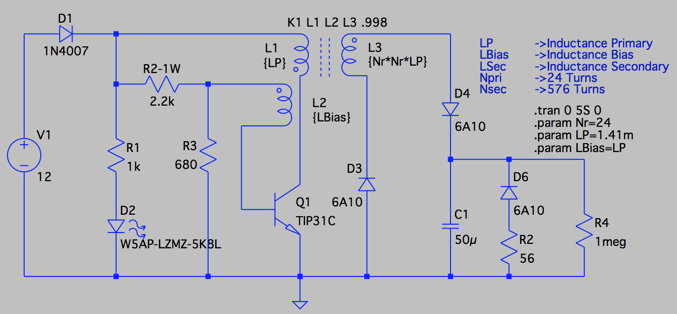
wanting to build the zapper but with modification to control max voltage before discharge, i simulated the circuit using LTSpice

the schematic without the output stage, only Inverter 12VDC to 600VDC
4758-0

the output Voltage
4760-1

without the Cap the Output is 1KV and with the Cap the voltage reaches 1KV after long time for the 50uFD it takes 3,18 Sec to reach 600V with the Value of R2->2K2 and R3->680.

The Primary inductance is a calculated value (http://powermagnetics.co.uk/calculator) with AL for E34 to be 2440 and AL for E49 = 3700 (without Gap) from datasheet (http://www.feryster.com/polski/e349.php?lang=en)  = 1.41mH and for E49 its calc to 2.1mH. The simulation is using turn ratio of 24 the Secondary Turns is 576 Turns (min 400 max 600 as per design Notes).

if i could get some help, it would be great

1. What is the measured value of L Primary 24 Turns on E34 & for E49. (without Gap..? hope this is also true)
2. Simulation show the Voltage across Cap is 600V @ 3.18 Sec ..? But the Fence Zapper is to Pulse every 1Sec and Diac breakdown is 600V..? hence in the simulation the trigger to the Triac would happen once every 3.18Sec and not 1Sec.

If the Inductance is available, maybe the simulation would be more accurate..? else If I would be the exact Period of the pulse I could trial n error to get the Inductance to match the period.

@ Oztules,

a) in the posting you mention that the R2 / R3 should be lowered for faster charge of the Cap. would you kindly inform do I decrease the R2 (2k2) or the R3 (680).? which is a better option.

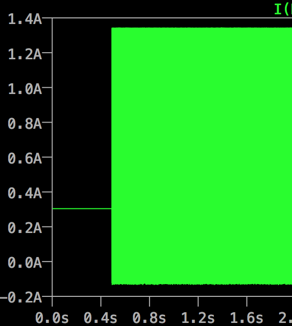
b) the current in D1 1N4007 is 1.34Amps.. which is greater than 1Amp Peak rating of the diode, but I guess because its pulses, this should not be a problem..? or should the diode be changed.
4764-2

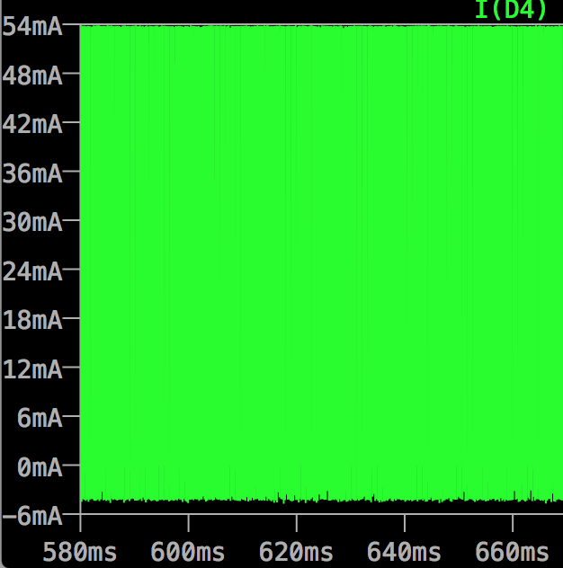
c) both the D4 & D3 the max current is 54mA hence David PCB with 6Amp Diode is not necessary and the IN4007 would do the job..?
4766-3

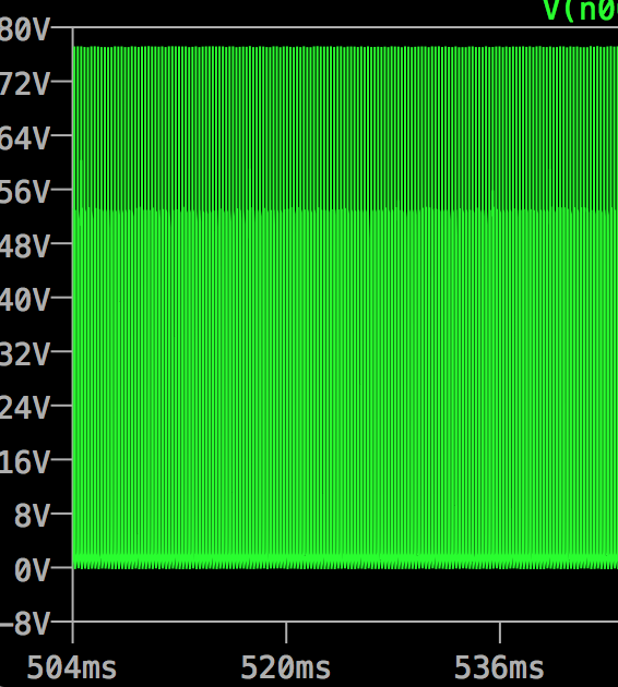
d) the Power in Q1 TIP31 peaks at 48W.. is this normal.. and the CE voltage is 77V which is below the Vce of 100V for TIP31C but above 60V for TIP31A ..?
4762-4

Thanks in Advance..

Regards
Srikanth Kamath
http://tskamath.pactindia.com