Author Topic: 30 LED array with cell phone charger driver  (Read 11123 times)

0 Members and 1 Guest are viewing this topic.

Offline MadScientist267

  • Impossible Condition Curator
  • Moderator
  • Hero Member
  • *****
  • Posts: 1514
  • Karma: +44/-4
  • Rules? What rules?
30 LED array with cell phone charger driver
« on: October 04, 2013, 06:58:45 pm »
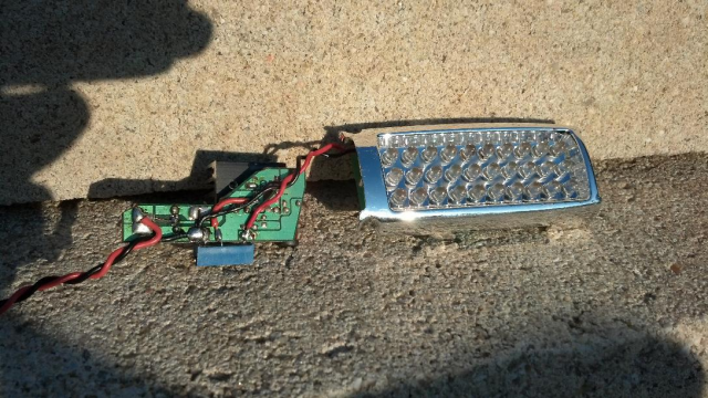
 Not long ago in IRC, Norm was looking for new ways to drive LEDs with various circuits...
2604-0

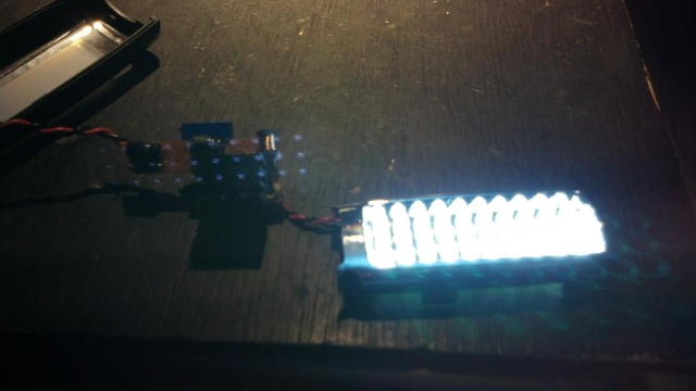
 Here's a typical example of what I've used here in the van for just that. Its a simple modification to a cheap run of the mill 12V car cell phone charger that's good for up to a couple of watts or so, a little more if careful attention is given to how the LEDs are arranged and a suitable heatsink is employed to help keep the converter chip cool.
2606-1

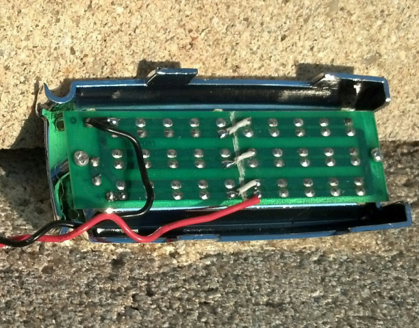
For this unit, I reconfigured the LEDs from 30 in parallel to two strings of 15 in parallel, with the strings then wired in series. This accomplishes a couple of things. First, it lowers the output current from the buck converter, reducing switching losses (and therefore heat) at a given power level, and second, brings the output voltage for the converter closer to the input voltage, which also helps increase efficiency.
2608-2

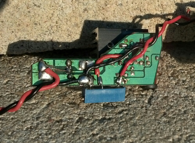
 To modify the charger to drive the LEDs, the original voltage divider (a set of 2 precision resistors) that sets the output voltage at 5V is removed and replaced with a 10k ohm, 15 turn precision potentiometer.  This allows precise control over the output voltage from about 1.2V to 10V or so (with a 12V input) using the chip that is in the chargers I'm using (MC34063). This easily allows for 1 or 2 LED strings, 3 if your input voltage is high enough. Typically, the output is a maximum of 2V lower than the input with this chip. So for example, if your input were 13.8V, the maximum you can set the output for is about 11.8V

 For smaller numbers of LEDs or single die LEDs of about 1W or so, no heatsink is required on the chip to drive the LEDs at full brightness. Above about 1W total, I highly recommend the use of one.
2610-3

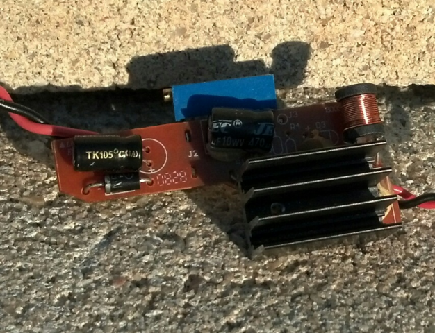
It doesn't need to be fancy, the sink pictured is an anodized TO220 heatsink from Radio Hack, epoxied to the chip. Note that there are no official provisions for a heatsink on a chip of this type, so it is not optimized internally to take advantage of one. It will however bring the temperature down to a more comfortable level while allowing a bit more power flow.

When first connecting the power, leave the LED(s) disconnected and place a volt meter on the output. Adjust the trimmer for just less than 3V for a single die or multiple LED array that is wired all in parallel, or around 6V for the two-LED string version. If you are using 3 in a string (and your input voltage will stay high enough during use), set it to 9V. Note the direction for increasing the voltage with the trimmer pot, and then connect the LED(s). Note that these voltages assume you are using white LEDs, which typically have a forward voltage drop (Vf) of about 3.2V. When first connected, the LEDs will barely glow, if at all, until the trimmer is adjusted to increase the voltage. If for whatever reason you're using a different color LED, make note of the rated Vf and set the trimmer accordingly before connecting them to avoid damage to the LEDs and/or converter chip.

Tip: The trimmer is marked "CW" on one end. The pin on this end of the pot should go toward the ground connection on the board. This ensures that clockwise rotation increases the voltage and vice versa.

Don't exceed the current handling abilities of your LEDs or the driver chip. Make small adjustments while monitoring heat in both the chip and LEDs. The chip can (and will) run much warmer than the LEDs. If the LEDs are of the garden variety "20mA" type (as I'm using here), there should be almost no heat coming from the back side of the LED board. Anything more than "can tell they're on" is too hot, and will drastically shorten their lifespan.

The MC34063 is a fairly robust chip, but not indestructible. By changing the output voltage, the current limiter has been knocked out of calibration and is less helpful in protecting the chip from overload. Sensible temperature checking while operating it over the course of about a half hour will ensure it stays in limits. If you can't hold your finger on the label side of the chip, it needs a heatsink. If you then can't hold your finger on the heatsink after it has a chance to warm up, the power level needs to be reduced until you can. Note that it can take time for the heatsink to "react" to the change... Make small adjustments and give it time, rinse, repeat. This is particularly important when increasing power, as the chip can go into runaway before the temp of the heatsink rises to an uncomfortable level.

 The astute eye would have caught "current limiter" mentioned above. Its nothing more than a single low value resistor (typically a couple of ohms) that's got a little more meat to it than the others. While this resistor can be changed to accommodate the new application, I've found that with careful adjustment of the trim pot, this is entirely unnecessary.
2612-4

 The rig pictured draws about 200mA or so with a 12V nominal input.

Enjoy!

Steve
Wanted: Schrödinger's cat, dead and alive.

Offline oztules

  • Forum Advisors
  • Hero Member
  • ****
  • Posts: 1177
  • Karma: +105/-8
  • Village idiot
Re: 30 LED array with cell phone charger driver
« Reply #1 on: October 04, 2013, 08:52:48 pm »
It's good to see both recycling, and that it works......

But gee, I would prefer to see current limiting rather than voltage limiting. LED's are current devices, not voltage devices. I would rather turn the attention to the current limiter, and sort that, and let the voltage run free if I had to.

I build a few underwater LED arrays for folks over here  for floundering etc, and always use current limiting.... but then they use a variety of batteries ( 12-18v from their drill kits, and they go from full to flat  too.

Precision voltage control will work well ........ as you have shown,.... but really it leaves me cold for LED lighting applications.... because we are pushing then pretty hard, not like a bezel application.

Just old fashioned... current limiting sources for current devices.... just seems better somehow.

Nice work all the same .


............oztules
Flinders Island...... Australia

Offline MadScientist267

  • Impossible Condition Curator
  • Moderator
  • Hero Member
  • *****
  • Posts: 1514
  • Karma: +44/-4
  • Rules? What rules?
Re: 30 LED array with cell phone charger driver
« Reply #2 on: October 04, 2013, 09:24:20 pm »
 Oz -

You're right, and when its present and doesn't require any modding, I utilize CVCC as a preferred method as well. With these, there's so many of them I have in use because I got a ridiculous deal (virtually free) on a bucket load of the chargers that I took the minimalist approach with them. They're literally everywhere in the van and hold their regulation so well that I've never had a problem... I just set them on the "cool" side to allow for tolerance shifts and they haven't given me any trouble.

For anything involving higher power (and therefore cost), CVCC is the way to go. I wouldn't design an expensive LED array and leave it to chance. But for the couple watt ranges that I've applied this to, it works well.

Steve
Wanted: Schrödinger's cat, dead and alive.

Offline Norm

  • Sr. Member
  • ****
  • Posts: 475
  • Karma: +26/-0
  • Today is the day you worried about yesterday.
Re: 30 LED array with cell phone charger driver
« Reply #3 on: October 05, 2013, 05:23:06 pm »
Okay Steve, I've noted your posting and Oz, your reply, and I understand the current
limiting part. Yes I would like to really have you refer me to one of your lessons
that I could apply to this "flying saucer thing" in the first place it has 20 LEDs in the outer ring
which is all I'm concerned about they seem to be paralleled with a resistor in series.
 originally it was run with 4 alkaline AA batteries in series.
A few months ago I ran this with one of these cell phone chargers (they output 5v) regardless
of input to it .
I noticed that when the source voltage was real high ...about 13.65  they got real hot
Not hot enough to burn ...but Excellent hand warmers !
......down at 11.5 -12volts they were just warm.
So in the future could a decent current limiter driver be made for these ?
this outer ring consist of 4 segments 5 LEDs each which can easily be separated
into 4 groups and paralleled series resistors  transistors and such separated into anything
smaller would be too tedious.
This particular  voltage limiter has a JYD 1118 chip
and like Steve says you can pick them up from goodwill 4 for a $1 or brand new at
Dollar Tree for $1.
appreciate your comments Oz !


....and  Steve how would 2 strings of 10 in parallel and then those 2 strings in series.....or
4 strings of 5 in parallel and then those 4 in series ?
 I'll have an easier job than you a simple matter of UN-soldering a few wires and rewiring
Then of course replacing those 2 resistors with a 10K potentiometer and like you said I don't think I'll need a heat sink.
well maybe I can talk to you on IRC tonight more about it then .
Norm.
   

Offline oztules

  • Forum Advisors
  • Hero Member
  • ****
  • Posts: 1177
  • Karma: +105/-8
  • Village idiot
Re: 30 LED array with cell phone charger driver
« Reply #4 on: October 05, 2013, 07:26:59 pm »
Norm, I think that was directed at me.....

Commanda at fieldlines wrote a very good article on LEDs... At the moment it is here; http://www.fieldlines.com/index.php?topic=131213.0

Because they will probably lose it soon, I will post a picture from her story, and her words as well.

Here is her diagram of a thermally stable circuit

2614-0

and here is her explanation of it.... it is quite simple and .... well... just what you want.

"
In circuit 4, we use a fet as a variable resistance element. Rg biases the fet on, current starts to flow in the fet, generating a voltage across Rs. As this voltage approaches 0.6 volts (Vbe of the transistor), the transistor starts to turn on. The transistor decreases the voltage on the gate of the fet, tending to turn it off. We now have a constant voltage across Rs (Vbe), and a constant drain current in the fet. Again, we run multiple strings of leds, each with their own little equalizing resistor (Req).


In practice, we now have the exact opposite of the previous example when it comes to heat. We bond the transistor to the fet. As the fet gets hot, the transistor Vbe decreases, so the voltage across Rs decreases, and the current through the fet decreases. We have now effectively prevented thermal runaway. There's a new concept for you, didn't mention that one before, did I? "

Somoapower also contributed a very useful picture as well, to circumvent one led in an array failing, and taking out that string, and allowing excess current into the paralleled strings.

2616-1

So one can fail, but the array does not crash. The leds need to be roughly matched for this, and he feels 10% is ok ( I'd go a bit further ).

Here is that circuit in practice on my lathe. It has a rectifier in there as well, but the regulator can be seen through the epoxy.
2618-2

2619-3


I can't find the other parts of her class, as fieldlines loses things... such as Woofer found her led series here, and posted links:

http://www.fieldlines.com/story/2007/4/20/95351/1614

http://www.fieldlines.com/story/2007/4/26/82929/6080

http://www.fieldlines.com/story/2007/5/1/74856/25992

http://www.fieldlines.com/story/2007/10/13/141930/41

http://www.fieldlines.com/story/2007/10/31/848/94375


But they seem to have gone missing in action.

With this circuit, the voltage can go anywhere it likes, providing it has enough EMF to get the diodes going for the string length, the voltage can rise as high as it wants, and current remains the same.  ( so chose transistors of a rating that  will be capable of handling the voltage swings.)


.......... oztules
Flinders Island...... Australia

Offline MadScientist267

  • Impossible Condition Curator
  • Moderator
  • Hero Member
  • *****
  • Posts: 1514
  • Karma: +44/-4
  • Rules? What rules?
Re: 30 LED array with cell phone charger driver
« Reply #5 on: October 06, 2013, 09:33:17 am »
 Unfortunately Norm, the 1118 (as far as I can tell at least) is a linear regulator. I can't find a "JYD" variant of it specifically, but there are numerous prefixes out there, that all seem to point to the same IC. My guess is there's a "-5" or something very similar following the "1118", indicating a fixed 5V output.

Essentially what this means is, its not really suitable for this application. Being non adjustable for one (at least not by design), and it doesn't convert anything, it simply "wastes" what it doesn't pass along to the load. This is in line with the excess heat you're seeing in it when driving it with higher voltages at the input. Half of your battery power is just going to be wasted as heat with this device.

 To be efficient, you need an actual buck converter. The batch I got were extremely cheap because they were part of a "closing the doors" sale at a Radio Hack where the manager had set up a "cram what you can into one of these boxes for 5 bucks" type deals, and there were something like a dozen and a half of them to be had. It's a rare thing of course, so I snatched every last one of them that I found in the pile, and got pretty lucky.

I've seen a couple of other one-off deals around in various grocery stores where they dropped them down to something like 2 bucks a piece, and when I see those, I grab them too.

I've nearly depleted my stash or I'd fix up a few and send them your way, but unfortunately I'm back on the hunt again myself. The one for the array above came from another LED assembly I had built some time back but was an early "test" build that really didn't need it as much as the 30 LED array. I use these little things for just about everything, LED drivers, brushless fan controllers, you name it...  Really handy to have around.

You might be able to find bundle deals for like a set of 10 or something for dirt cheap on places like fleabay, dunno... Although the shipping is likely to be as much as the chargers :/

If you can find some, we can certainly go from there, I definitely don't mind helping you determine the mods to be made so that you can get something built.

In the mean time, there's still the joule thief, you're just looking at a different way of feeding it in that case. ;)

Steve
Wanted: Schrödinger's cat, dead and alive.

Offline Norm

  • Sr. Member
  • ****
  • Posts: 475
  • Karma: +26/-0
  • Today is the day you worried about yesterday.
Re: 30 LED array with cell phone charger driver
« Reply #6 on: October 07, 2013, 09:36:49 am »
okay Steve ....here is the pic had a hard time figuring out the resistance of
the little critters so finally I just gave up think the battery is low so you'll have to guess
bands too small for me to read the colors. I'd need a jewelers lope.

so here it is 2620-0

Offline WooferHound

  • Technowhiz
  • Global Moderator
  • Hero Member
  • ******
  • Posts: 897
  • Karma: +40/-3
  • Huntsville Alabama USA
    • My personal webpage
Re: 30 LED array with cell phone charger driver
« Reply #7 on: October 07, 2013, 03:20:27 pm »
I'm not sure if this is one of the energy wasters that y'all are talking about, But I have used this Current Limiting circuit a few times on my LED lighting projects.
It uses a LM317 in current limiting mode and only requires one resister to make it work. Simplicity at it's best.
http://www.reuk.co.uk/Using-The-LM317T-With-LED-Lighting.htm
----- W o o f e r h o u n d -----
My Renewable Energy Projects

Offline oztules

  • Forum Advisors
  • Hero Member
  • ****
  • Posts: 1177
  • Karma: +105/-8
  • Village idiot
Re: 30 LED array with cell phone charger driver
« Reply #8 on: October 07, 2013, 04:16:32 pm »
Yes Woof, thats a linear device.... energy burner.

Norm, your board features a buck converter... same as Steves.... so your chip is a DC DC converter... and from the circuit I suspect it is a MC34063A with apparently different name ( the JYD1118)...pin for pin looks equivalent.


You should be able to let the voltage run free, and use the Rsense resistor to limit current to what you want... so can Steve for that matter.

You have a coil on the board... thats the give away... looks like pins 1-2  is the switching transistor.... ie

Pin 1 has the switch collector
Pin 2 has the switch emitter
Pin 3 has the cap for the oscillator freq
Pin 4 is ground
Pin 5 is comparator input  ( inverted) for voltage control in this case controlled by 1R and 2R Possible value around 3k and 10k respectively
Pin  6 is your input V
Pin 7 is your I sense pin ( stops the waveform of the osc if > set) Sense voltage set from the voltage dropped in R4.
Pin 8 is your driver collector ( connects to pin 1 and 7)

Pic is a bit fuzzy to me.
R3 drives your Red led.

Typically, I expect R4 to be around .33R for 1A short circuit... so if it were replaced with say 2ohms, we would see probably about 180ma.... remember this is a guess.

Start with ah high resistance ( 10 R) and see what current you get, and calculate from there.

...........oztules
Flinders Island...... Australia

Offline Norm

  • Sr. Member
  • ****
  • Posts: 475
  • Karma: +26/-0
  • Today is the day you worried about yesterday.
Re: 30 LED array with cell phone charger driver
« Reply #9 on: October 07, 2013, 06:10:06 pm »
Thanks Oz, so I guess that will fix it .
the R4 by the spring changing it will propably do it?
a variable resistance like a potentiometer .....of what range then ?
at present it looks like red, green, red , silver, and silver ?
I'll check and see if your guess is close ......
and thanks a lot...
good thing these are only a $1 apiece....
those flat pieces of tin .....that spring....the red led and resistor
all very useful for my other products even if I goof up !
thanks again !
Norm.

Offline oztules

  • Forum Advisors
  • Hero Member
  • ****
  • Posts: 1177
  • Karma: +105/-8
  • Village idiot
Re: 30 LED array with cell phone charger driver
« Reply #10 on: October 07, 2013, 07:43:34 pm »
"the R4 by the spring changing it will propably do it?"..... yes

But you will have to raise the voltage to overcome the step off of the diodes... depends on the string length.

1R and 2R control the voltage. If you decrease the value going to ground. you will fool the invert input into thinking the voltage is lower, so it will raise it.
Thats how we change the voltage.... or increase the one going to the output, so the earth resistor attenuates it much further than now... and the chip still thinks the voltage is lower than it should be.

A pot will not be easy to find in the 0-10 ohms .... so really it will be .. put a higher resistor in there, calculate the voltage drop it puts on pin 7 to effect current limit.

Then work out your current requirements, and chose a resistor that will drop the that  voltage across the newR4... and get that value or make it up via a few in series/parallel etc.

The data sheet tells us that it is about 300millivolts to trigger the current cut off. The voltage comparator is 1.25volts.

So your R1,R2 voltage divider needs to give pin 5    1.25v for the upper voltage limit you want. ( an ohms law thing to get the two resistors you want for this divider)

R4 needs to see 300mv drop over R4 in order to trigger an interruption to the present square wave  cycle ( and so limit the current by cutting it short).

So if your array was to take say 200ma at whatever volts, we need to see 300mv drop over R4 @ 200ma.. or .2amps. R=E/I or .3/.2=1.5 ohms... etc etc etc.

Simple theory explanation.
The chip oscillates at high frequency. The width of the pulse it send to the coil dictates the energy that it transfers to it. Wider pulse more energy etc.
So to control voltage ( if we want) we use pin 5, measure the output voltage through the divider of R1 and R2, when it sees 1.25v, it shuts down the width, if it drops below 1.25 it increases the width.

For current., when pin 7 sees 300mv, it is linked to the oscillator, and resets the flipflop driving the output transistor. This truncates the current/present cycle ( which was set by the pin 5 voltage limiter.... it over rides the voltage comparator, and concentrates on the current if it goes over threshold setting.

So it sets the voltage as best it can, but it can be over ridden by the current sense, as it could be a short, or could be just current limiting.

Thats how I understand it anyway.


..............oztules
Flinders Island...... Australia

Offline MadScientist267

  • Impossible Condition Curator
  • Moderator
  • Hero Member
  • *****
  • Posts: 1514
  • Karma: +44/-4
  • Rules? What rules?
Re: 30 LED array with cell phone charger driver
« Reply #11 on: October 09, 2013, 11:38:04 am »
Quote from: oztules
A pot will not be easy to find in the 0-10 ohms .... so really it will be .. put a higher resistor in there, calculate the voltage drop it puts on pin 7 to effect current limit.

Then work out your current requirements, and chose a resistor that will drop the that  voltage across the newR4... and get that value or make it up via a few in series/parallel etc.

The data sheet tells us that it is about 300millivolts to trigger the current cut off.

So rather than set a precision voltage, we're going to get the current "close enough" by wedging between the granularity of some low value resistors?

Jeez, if you're going to over complicate something, at least complete it...

2622-0

The 1K sets the current limit. CW and CCW are clockwise and counterclockwise respectively. Start at full CCW. Choose Rs for the next highest value available that would give you a current *below* your target if it were used by itself. The trimmer can then raise the current up to the precise level required.

The original voltage divider modification is also shown. If you want to go with current limiting alone, omit the 10k trimmer and just tie pin 5 to ground instead. This will cause the chip to run at 85% duty cycle until the set current is reached. In your case Norm, the resistors you'd be replacing/omitting are R2/R3 per your picture. EDIT - Correction, agree with Oz, R1/R2

Its really unnecessary to go with the current limiting in this case, makes for a bunch of extra work, and doesn't accomplish anything that the simple voltage tweak doesn't do. We're talking a handful of cheap LEDs here, not a $100 array with a finnicky warranty. But there are the required mods, either way you decide to go.

Steve
Wanted: Schrödinger's cat, dead and alive.

Offline oztules

  • Forum Advisors
  • Hero Member
  • ****
  • Posts: 1177
  • Karma: +105/-8
  • Village idiot
Re: 30 LED array with cell phone charger driver
« Reply #12 on: October 09, 2013, 12:52:12 pm »
Steve,

Now you have now turned it into a useful project. You have a current controlled, voltage selectable universal power supply...

It is now a useful device to have on hand for a lot more things. The current limit now allows it to be used for experimenting in particular.
It can limit the amount of times and severity of the magic smoke getting out of the box when testing the next widget.

Well done.


.....................oztules
Flinders Island...... Australia

Offline MadScientist267

  • Impossible Condition Curator
  • Moderator
  • Hero Member
  • *****
  • Posts: 1514
  • Karma: +44/-4
  • Rules? What rules?
Re: 30 LED array with cell phone charger driver
« Reply #13 on: October 09, 2013, 04:33:19 pm »
 I'm going to toss one thing out there... I haven't *built* the circuit described in the schematic...  or at least the current limit adjustment section.

There's no "official" documentation available from datasheets that describes such an arrangement. It IS however based on other circuits that accomplish similar feats, albeit without the "variable on the fly" aspect incorporated. A pot therefore isn't a stretch to make it so.

That said, I'd recommend a less sensitive load (power resistor?) and an ammeter in line with it for initial power up tests, to make sure that the circuit behaves as expected.

The biggest issue is that the current limiting control for the MC34063 isn't to protect the load, it's to protect the chip.  Varying supply voltage is going to cause varying current at the output under limit conditions, since the tendency of the circuit as a whole isn't constant voltage OR current, but constant POWER.

Without a bunch of trickery, getting the current sense to work on the output instead of input isn't possible from where I sit. It would need a separate error amplifier that is then "hacked in" to feed the sense pin what it needs to see to limit the current. Just not worth it. Its much easier just to set the voltage a bit below the Vf and underdrive the LEDs to protect them instead. Keep the chip reasonably cool and it doesn't drift that bad, really. Leave extra margin to cover paranoia.

Now you see why I said it wasn't really worth it. The MC34063 is a quick and dirty chip, and isn't set up to do anything fancy. TL494 or KA3525 are both much more versatile, but I don't have to tell you, with versatility comes complexity.

Steve


Wanted: Schrödinger's cat, dead and alive.

Offline oztules

  • Forum Advisors
  • Hero Member
  • ****
  • Posts: 1177
  • Karma: +105/-8
  • Village idiot
Re: 30 LED array with cell phone charger driver
« Reply #14 on: October 10, 2013, 12:11:42 am »
Unfortunately, I don't have any of these chips, so I can't prove the following, but looking at the data sheet, one can assume these observations.

1 It is an unusual set up from the op amp point of view. I suspect it is a high gain comparator, rather than a gain compensated op amp.
By this I mean that there is no provision for gain control from the op amp.... why is this?..... because it does not produce PWM from the one comparator in the block diagram.

2. The chip does not produce a pwm wave form in the usual way. It outputs the result of the comparator as a 1 or 0... why do I think this? Well, it goes into a And gate... it is a logic gate not an analogue thing, it is a yes or no thing.

So the comparator is effectively 0 or 1 to the And gate, depending if the voltage is higher than the set voltage ( 1.25) or lower, there is no useful in between, as the And gate only sees 1 or 0.. or actually only outputs 1 and 0. It will ignore lower than X volts and act on greater than Y volts.

3. The And gate then drives the rs flip flop. That  can only produce an output on the Q output, if R is 0 and S is 0 or R is 0 and S is 1... all other combinations are 0 on the Q output.
This makes for an interesting looking pulse train....

This means that the oscillator outputs a constant pulse width, not a saw tooth into a comparator as you mused with the TL494 or op amp generated pulse widths, these waves are symmetrical....and are there or not there.....unless the Ipk kicks in and truncates them ( pwm's the clocks pulse width ) to the RS and the And gate I suspect... never seen this style before.... but lets keep going anyway.

So to regulate voltage  only, it can only output fixed waves or no wave at all, and by shuffling between states, produces an output with some hysteresis, as it can only see what has happened and then make plans for the future in light of this.

So it looks like  a bang bang style unit when only voltage controlled.

Now the current limit is attached to the clock. If Ipk is greater than 300mv or there abouts, it changes the width of the pulse sent out from the clock ( pwm) ... very similar to the scenario you referred to with normal voltage style comparators like the 494.

On startup, the output cap will be a short circuit, and the chip will attenuate the peak currents with this control... why not use it normally.

I note that the data sheet gives a range for the Ipk, so it looks slope style.. in fact it leads me to believe that this little chip will work faster/smoother as a current driver than a voltage driver.. ie cycle by cycle control rather than delayed control via the bang bang voltage comparator after the event.

To this end, your little circuit could be a very useful circuit for driving THIS led array as variable/dimmed LED array, with a set MAX current for diode array protection, and a "volume/voltage control" for the dimmer function.... no precision needed, as at full tilt, it would current limit, and anywhere under would produce light at the attenuated voltage. if it is difficult to control the 300mv manually
nifty.


I think this chip deserves some experimentation, as it could do all you want from 40v down up to 1.5A if you can dissipate the heat, or use an extended driver transistor on the output.... would be interesting to do.

No concrete idea if I'm right, but it looks to work like that.... if you know more about this chips operation than my guess work, or have measured the wave forms under varying conditions, I'm all ears.

Never seen this style before... looks interesting and tough.

"Varying supply voltage is going to cause varying current at the output under limit conditions, since the tendency of the circuit as a whole isn't constant voltage OR current, but constant POWER."..... this makes no sense to me Steve. Only if Vcc approaches Vout will the regulator misbehave... droop... otherwise it is not regulating at all. If the load is increased somehow ( another string?), providing it does not hit current limit, it should be stable, else run at I max and V will droop.
Your V is controlled by the 1.25V ground reference, and so ignores Vcc, until it drops to Vout ( plus  some overheads for transistor and coil efficiency) as does Ipk via the 300mv through the Rs resistor...... neither reference the Vcc, except the voltage divider giving the  error voltages to the comparator... and thats what regulates it in the first place.

.................oztules


Flinders Island...... Australia