All the photos here (and more that I won't post) can be viewed in the album for this turbine here:
http://www.anotherpower.com/gallery/ferrite-magnet-MPPT-turbineThe first photos start out with the gearbox design and layout. I had decided early that this turbine was going to use an angled hinge tail, with the tail working against gravity, for the furling system. So I offset the PTO shaft in the gearbox to move the generator slightly away from the yaw axis, and thereby allow more room for the tail hinge. In the end, this worked out quite well.
The gearbox has a .400:1 gear ratio, meaning the turbine's generator runs at 2.5x input shaft speed.
My original idea with a MPPT-controlled wind turbine was to use a Midnite Solar Classic 150 controller on a 3.8 meter turbine, with a dual stator ferrite generator, modified with high voltage stators. I tested this setup (with a stock stator set) with a hydraulic motor driving the turbine's gearbox input shaft, with the Classic 150 hooked up, and a "real world" wire run to my battery bank, to get an idea of how the controller works and how a stock 24V generator pans out with MPPT on it.
What I learned was that it is quite easy to get 2.5 kW out of this setup with way less shaft power input required than what a 3.8 meter rotor can deliver. I discovered I don't really need the raw amp capacity of the dual stator generator, but I could use more voltage input to the controller to make the gen, rectifier and wire run more efficient.
I think it was about that time that I decided to downsize the turbine to 3.2 meters and use a different style of blades on than GOE222's (which is what I had used on previous turbines).
So I went to my CAD (Cardboard Assisted Drawing) design system to look at possibilities for a generator for it:
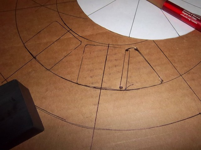
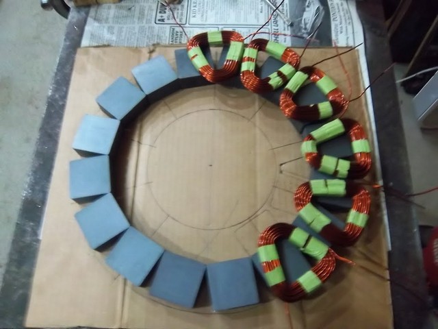
I initially looked at 10 pole stacked two-phase layouts. But then the light bulb came on over my head one cold night and I decided to figure out a three-phase single stator layout that would give me adequate amps and more volts for the amount of rotating mass and copper used in the generator. This is a CAD layout of coils that were actually wound for a 10 coil single phase stator. But the pin dimensions and volt turns ended up working out fine for a 16 pole 12 coil three phase design, as well - with the added advantage of getting more volts out of the thing:
Based on my testing run, I developed a spreadsheet to figure out how to match rotor rpm and available shaft power to rpm/volt from the generator, and to the load. My initial idea here was to have 119 open volts @ 400 rpm. But later on in the build, after studying the NREL testing data on the S809 airfoil that I'm using, I decided I needed to run the rotor faster (480 rpm @ 12.5 m/s) to get enough shaft input power to make a 2.5 kW turbine out of this thing. I made a YouTube video explaining that decision that you can watch (hope this YouTube thing works - couldn't get it to come up in the Preview)
--
Chris


