I thought I'd put this up already, but it seems not!
A few years back, I wanted something to monitor more closely what my aging and dying battery bank was doing. Simply monitoring the bank volts was proving inadequate, and being AGM I couldn't monitor SG. Also, as an active bank, trying to measure them with a DMM was pointless, because they never had the same conditions.
Commercial systems at that stage were stupid money, and honestly weren't going to do all that I wanted. So I set out to make my own.
The design was simple:
* I wanted to monitor nominal 2V (lead-acid) and 3V (lithium) cells.
* I wanted better than 10mV resolution.
* I wanted the option of measuring temperature of each cell.
* I wanted low-price, readily-available components, and nothing too tricky.
* I wanted something that would do 12V, 24V and 48V systems
* I wanted something that could be upgraded without having to scrap it all and start again.
* I wanted something I could connect to to automate monitoring, logging and alarming.
In the end, I decided that 10-bit ADC was all I was going to get in cheap microcontrollers, so I had to think of a clever way
to get a decent precision out of them. I decided each board would monitor only two or three cells. This would let me use a cheap PIC, measure temperature and voltage, have IO for serial communications and some indicator. Differential amplifiers let me get the full 10-bits for each cell, without dividing (and losing precision). That's under 5mV resolution. So by cascading (daisychaining) boards, I could have 2 boards (each with 3 channels) for a 12V system, 4 boards for 24V or 8 for 48V, and somewhat fewer for lithium based banks. One board would be a "master" and talk RS232 to a host system, the rest would just connect in a chain.
So, in no particular order, here's the pics.
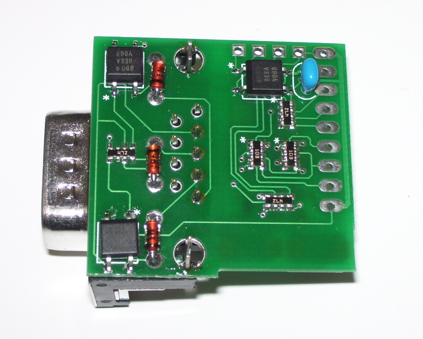
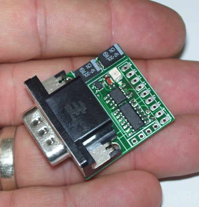
The "master" board. This is identical to all the others except it has the D9 connector and isolation circuitry.
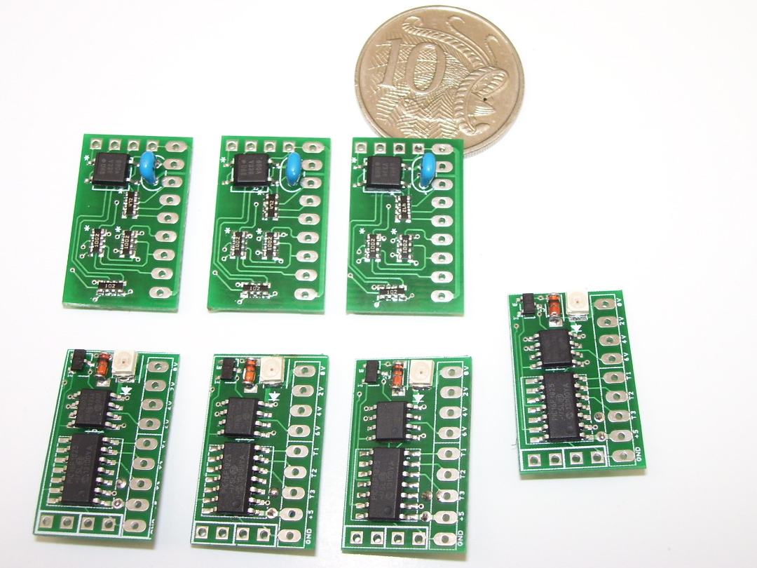
The other boards, shown here with a 10c coin for reference, are identical except they're missing the D9.
For my first application, I just made some simple clip-on cable sets.
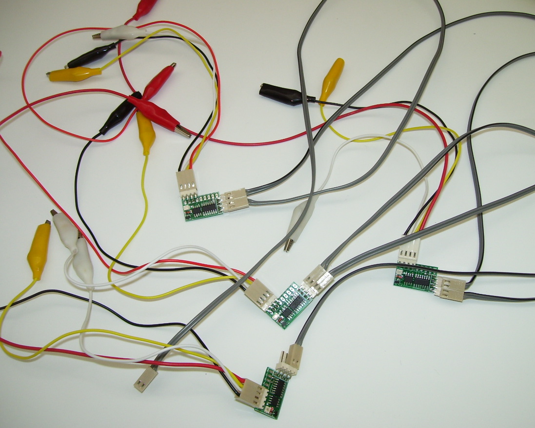
These allowed me to test the concept on an existing bank, without having to do anything.
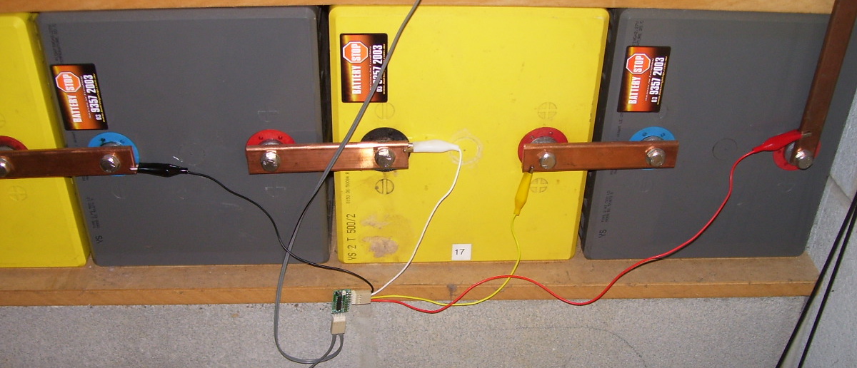
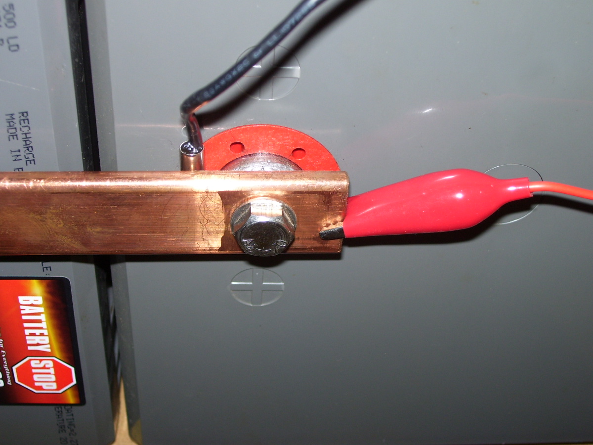
Temperature sensors are just DS18B20 chips in stainless sleeves, filled with epoxy. It was convenient to just slip them between the battery and jumper to measure the battery post temperature.
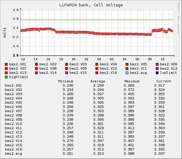
A reasonably typical display of the output from my AGM bank looks like this:
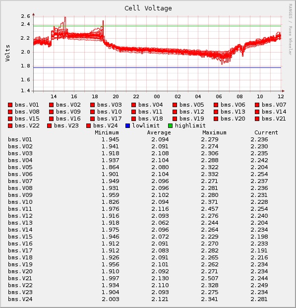
The LFP bank looks much nicer though: