Well, dug a module out of that monster switching supply, and honed it for use as a bulk slave for use here in the van.
These little buggers are pretty impressive... 13.8V @ 20A continuous each, the original cabinet had 3 of them in it.
They are loaded with everything they need to function as their own independent supply... Each module contains PFC, EMI filtration, overload protection (CC mode @ 25A), "masterless" slaving (current sharing buss), and even their own minimum load resistor, 100R/5W. They're simple, single sided, well thought out, and are happy to perform. Just gotta keep em cool. They are of a forwarder design, kind of surprising to me, given that there are better suited topologies for power levels in this range. But I'm not complaining, they work, and well.
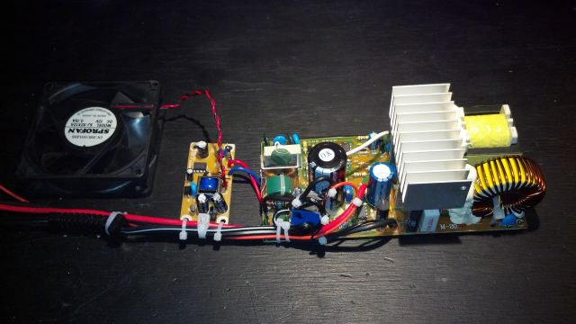
Here's some shots of the module and the mods I made to bring it into a life in and of its own as an assistant charger for the smart charger I built years ago. It sends a +12V remote signal via single wire to the module to turn it on, sourcing its ground from the module itself. I've also added a dedicated fan supply, so that the fan isn't just putzing along when its not needed.

The component side, fan supply is the small board to the left. The remote control consists of nothing more than an everyday 12V relay slipped into the mains hot side.

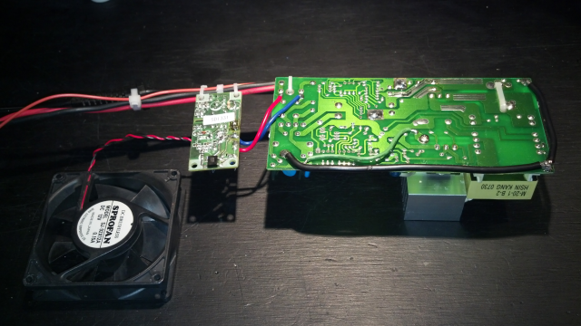
Trace side. The two heavy black wires satisfy the modules need for a "ground" path. I put that in quotes, as there is no actual ground connection anymore, it simply ties the various EMI components to a common rail that is fed back to the neutral lead (as was by design). I omitted the ground because it served no purpose anymore as a safety device, and would have only provided a path for EMI to be dealt with, something that the neutral run can deal with sufficiently for my purposes. Wouldn't be the first noisy device installed in this thing, by far haha

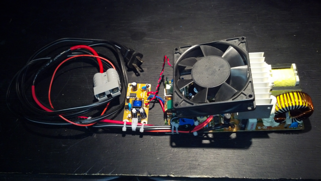
Detail of its basic layout as it will sit in the final installed version.

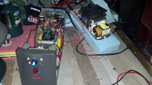
Doing its thing during the test run, slaved off the smart charger. Collectively, they are putting about 40A into the 235Ah bank in this pic.
Steve