Author Topic: CRT Flyback based air scrubber  (Read 9112 times)

0 Members and 1 Guest are viewing this topic.

Offline MadScientist267

  • Impossible Condition Curator
  • Hero Member
  • *****
  • Posts: 1514
  • Karma: +44/-4
  • Rules? What rules?
CRT Flyback based air scrubber
« on: February 10, 2013, 05:46:29 pm »
(this is a reference thread for IRC)

I want to take this:

1931-0

.... and use just the flyback transformer with some form of the "joule thief" circuit, to run on 12V nominal.

Steve
Wanted: Schrödinger's cat, dead and alive.

Offline MadScientist267

  • Impossible Condition Curator
  • Hero Member
  • *****
  • Posts: 1514
  • Karma: +44/-4
  • Rules? What rules?
Re: CRT Flyback based air scrubber
« Reply #1 on: February 10, 2013, 11:12:28 pm »
Sanity check, por favor...

1934-0
Wanted: Schrödinger's cat, dead and alive.

Offline MadScientist267

  • Impossible Condition Curator
  • Hero Member
  • *****
  • Posts: 1514
  • Karma: +44/-4
  • Rules? What rules?
Re: CRT Flyback based air scrubber
« Reply #2 on: February 10, 2013, 11:36:12 pm »
Bipolar version (IIRC)

1936-0
Wanted: Schrödinger's cat, dead and alive.

Offline frackers

  • Full Member
  • ***
  • Posts: 239
  • Karma: +9/-0
  • If it moves - computerise it!
Re: CRT Flyback based air scrubber
« Reply #3 on: February 11, 2013, 07:13:40 pm »
Winkle the power supply from a broken plasma ball - they run about 15KV from 12v and use a flyback TX
Robin Down Under (or are you Up Over!)

Offline MadScientist267

  • Impossible Condition Curator
  • Hero Member
  • *****
  • Posts: 1514
  • Karma: +44/-4
  • Rules? What rules?
Re: CRT Flyback based air scrubber
« Reply #4 on: February 12, 2013, 03:29:00 am »
I actually have the pseudo-translation for MOSFET of the bipolar transistor version built and running, but it's HIGHLY inefficient and the tranny gets hot in short order (then again, hasn't been mounted on a heatsink yet either)...

It was a quick and dirty gear shift from another circuit that Ross found on instructables, but either I did something wrong (entirely possible) or the guy just got really lucky with his combination of parts... either way, it wasn't working, was trying desperately to smoke the MOSFET, and only required something like swapping 2 wires and adding the other half of the coil I wound to get the feedback to drive it.

I didn't bother drawing anything up on it... lack of sleep has taken over again (hopefully briefly), and I walked away while there was still a functioning transistor to work with haha

There are several improvements however that have been tossed around, I'll be trying those out shortly. One is to try driving the flyback as a pulse transformer instead of a true flyback.

One of the major goals with this was an extremely compact supply that had next to no parts (which the "hartley" above certainly qualifies as)... and could be built with nothing but what was on hand... The transformer simply fell into my lap when the neighbors across the street tossed their fully functional 19" TV. When it's all said and done, the entire scrubber will ideally literally cost nothing to build.

More as it happens ;)

Steve
Wanted: Schrödinger's cat, dead and alive.

Offline MadScientist267

  • Impossible Condition Curator
  • Hero Member
  • *****
  • Posts: 1514
  • Karma: +44/-4
  • Rules? What rules?
Re: CRT Flyback based air scrubber
« Reply #5 on: February 12, 2013, 09:33:47 pm »
Well, so much for simple... But free still applies!  8)

There are still some vague bugs to work out, but I've found the trends, and really just need a few pots where there are fixed resistors so I can dial it in and wrap it up that much quicker.

The spark in these pics is about 3/4", and are "static" in nature, however I was also (at this gap) able to draw a hot arc. I wanted to get a picture of that as well, but noticed that it was being pushed to the limit, and was trying to let the smoke out (in fact it sprung a very small leak, my clue that I was pushing too hard on it). I've made 4 tweaks at this point, each one involving a significant improvement in output.

These were shot at 12.7V set on the buck/boost, current unknown, however in "scuff your FET" mode (get it? :P), nothing shows the first sign of heat anywhere, and that gigantic heatsink could likely go completely missing and the tranny wouldn't be but lukewarm. ;)

What you're looking at, left to right, is the bias pot (not exactly in the traditional sense, more down the line on that), the buck/boost, the heatsink with a cell charger buck board that I have gotten very friendly with (I have tons of that model, use them for everything), the flyback (the lone resistor is a 470k... I was having problems with static discharge between the two pins its attached to, and didn't want to risk insulation breakdown anywhere, so this gives it a safe place to go without affecting the desired functionality), and the gap of course with what I hope is a worldwide standard utility blade below it for scale.

1959-0

Here's the gap close up...

1961-1

Not bad, and it puts out ozone like crazy, which is one of the capabilities I am after for "deep scrub" mode (the human leaves the area for that process hehe)...

Progress made. Its still free, its MUCH smaller, and will be able to do the job!

Once I get it dialed in, everything will be sandwiched between the heatsink and flyback, and all the little parasites trimmed out as much as possible. ;)

Steve
Wanted: Schrödinger's cat, dead and alive.

Offline MadScientist267

  • Impossible Condition Curator
  • Hero Member
  • *****
  • Posts: 1514
  • Karma: +44/-4
  • Rules? What rules?
Re: CRT Flyback based air scrubber
« Reply #6 on: February 13, 2013, 04:19:53 pm »
Ok, a few tweaks later, and put back up on the foam, and lets just say <cough, hack, wheeze> ...  It works. ;)

This is by no means the final form, but gives me enough to work with that I can get a really good idea of how the supply performs and what I need to do to finish dialing it in.

There are 4 pots ATM, may or may not bother putting a 5th on... It would closely track one of the others, so there's likely little point. They are B+ voltage, buck chip drive (adjusts the bucks output into a 220R dummy load at around a few volts to adjust the duty cycle), MOSFET bias, and gate drive.

The gap is currently about 1.5" and has scrubbed all visible traces of smoke from the air (measured by how it glows under the bench lights), completely and totally in all of about 3 minutes time.

1963-0
The ion gun. It's set up to focus the particulates toward the center of the capture plate. The center pin it's shorter than the outer ring, the result being that the particles flow more inward as they leave the field around the needles.

1965-1
Mounted and running.

Steve

Wanted: Schrödinger's cat, dead and alive.

Offline MadScientist267

  • Impossible Condition Curator
  • Hero Member
  • *****
  • Posts: 1514
  • Karma: +44/-4
  • Rules? What rules?
Re: CRT Flyback based air scrubber
« Reply #7 on: February 26, 2013, 11:43:34 am »
Morphed the ion gun a bit... In the quest for the better dust trap ;)

The central element (grid) is floating and takes on a charge that is a product of the fields surrounding it.

2047-0
From the side... Gap between anode needles and cathode plate is about 6 inches.


2049-1
From above, showing the angle of the cation needle. This helps neutralize the field so that the charged particles aren't so rowdy and are better captured by the plate.


2051-2
Angle from below, showing the shape of the anode needles and the anion needle dangling from the grid... This helps the bottom side of the collection plate capture particles.

Steve


Wanted: Schrödinger's cat, dead and alive.

Offline MadScientist267

  • Impossible Condition Curator
  • Hero Member
  • *****
  • Posts: 1514
  • Karma: +44/-4
  • Rules? What rules?
Re: CRT Flyback based air scrubber
« Reply #8 on: March 18, 2013, 01:12:15 am »
 Mark III of the ion gun...

I've separated the HV supply and the scrubber now, as it looks promising that the supply may find another use in the heat of summer... But that is still in the works.

In the interest of space, I've also made another version of the ion gun... It makes a couple improvements over the first version, but also does not seem quite as efficient in its collection ability. Only time will tell there.

This gun produces a lot less ozone (unless I want it to, in which case it can and will readily produce massive quantities of the stuff). It also has about the same collection surface area that the original gun had (without the screen).

I believe at this point there is a strong correlation between the intensity of the corona discharge (and therefore ozone) and its ability to trap unwanted material in the air. If this is the case, no combination of collector config and high voltage settings will resolve the problem. This new gun hasn't been in operation very long, and still needs a few tweaks (the needles need to be razor sharpened for example), but does a reasonable job from what I can gather of cleaning the air, with the biggest benefit being its size.

Another one of the more challenging issues faced in the development of this is air velocity. In this design in particular,  the air tends to move so quickly that the particulates fly right past the collection plates. The theoretical fix is to use a  higher "capture" voltage to attract the particles more strongly to the plate, but this has the added effect of accelerating the air as well. The higher voltage also leads to a greater ozone production, but without any benefit.

One method I've played with is "steering needles" - the use of floating electrodes means that I can derive an intermediate voltage easily, then "borrow" some of that potential to push back on the air as it makes its way through the gun. This is easier said than done however, as there are another set of caveats associated with this method. It causes high pressure zones around the steering needles, which can cause a would be trapped particle to be violently ejected out of the side of the gun, never reaching the target.

In the shot below, there's only a single floating electrode; the target (heatsink on the right). There is no steering going on here yet, just borrowing some potential from the main anode lead to give the target a couple thousand volt potential in relation to the ground (acceleration/neutralization tube, center).

The other thing that has been solved in this design is the near neutralization of ions leaving the gun. The surrounding charge dissipates quickly within a few inches of the heatsink,  as opposed to several inches (and even as much as 3 feet with the old gun!)... An important consideration with a laptop just a few feet away.

2075-0

 I've improved my static field and ion detection probe as well, more on that in another post.

Steve
Wanted: Schrödinger's cat, dead and alive.

Offline MadScientist267

  • Impossible Condition Curator
  • Hero Member
  • *****
  • Posts: 1514
  • Karma: +44/-4
  • Rules? What rules?
Re: CRT Flyback based air scrubber
« Reply #9 on: March 21, 2013, 01:37:14 am »
I'll explain the post later

EDIT -

I have problems posting with the phone now after an update, and its unpredictable. Sometimes it wants to cooperate halfway decent, other times just getting a sentence out is a very painful process. Right now, its behaving, so here's the explanation, as promised:

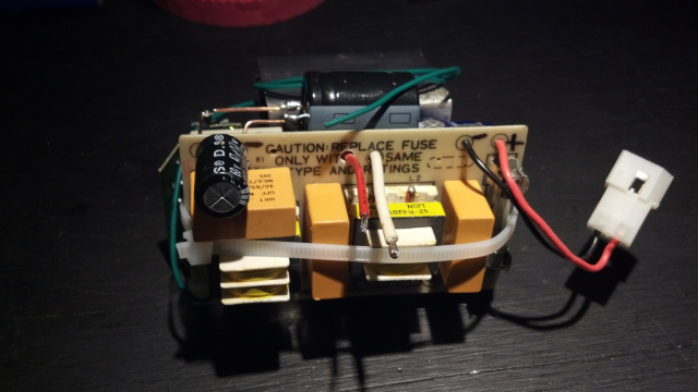
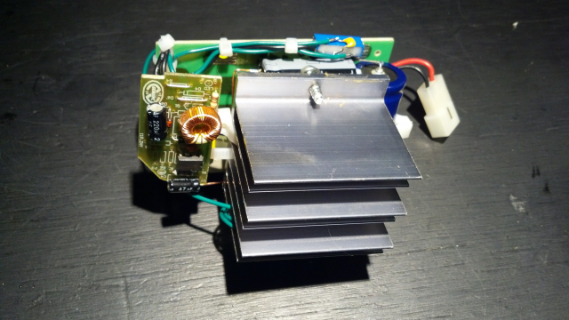
I've rebuilt the flyback driver, as a short time ago, the buck boost module I was using to dial it in got a bit on the warm side, and I ended up fusing one of the schottky diodes on it. Result was, I could still buck, but couldn't boost, and it was drawing a LOT of extra power. So I ditched it.

I had settled on about 18V for the supply for the driver before this happened however, and have a few old 19V laptop bricks laying around, and so just decided to use one of those. To protect it, and reduce EMI, I built a small filter based around a counterwound inductor like those commonly found in AC filters. It worked fine as far as filtration, but the output cap was getting extremely hot (uncomfortable for even me to touch, and I am known to be able to keep fingers on hot objects long after most let go). I decided I had to do something before it vented and left me with yet something else to deal with. The driver had also become very unstable even though the output cap was more than twice the capacity of the one on the buck boost.

What I came up with centered around the same concept as the first filter, but is much more robust. Overkill even. There are now 2 counterwound inductors, and a myriad of both electrolytic and X2 pulse rated caps to deal with the mayhem this device presents to the supply rail.
2095-0
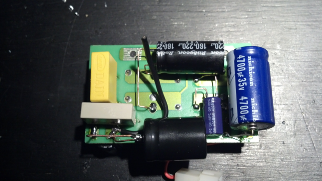
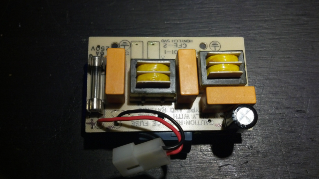
The backside of the new filter. The basic filter came from an ancient XT PC power supply, as it was constructed on its own board, and had all the baseline requirements already in place. I simply expanded on it. The unmarked cap at the bottom is a 330uF 200V main filter cap for switching supplies, it still warms up just a touch, but is in no danger of letting the smoke out. The caps go down progressively in voltage and up in capacitance as they get further toward the input of the filter. All of the others run cool.


2097-1
Another shot.


2099-2
And another...


2101-3
Here the driver is essentially assembled, without the flyback attached.
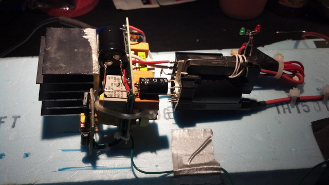


2103-4
The assembled driver with the flyback connected. I tamed it down a bit - many of the pots have been replaced with fixed resistors, and the only pot that remains controls the gate drive on the MOSFET.

 The increase in performance was astounding after the redesign... I could pull 3 inch sparks before I did some further adjusting on the fixed resistors, its now down to an inch again at full throttle. Even this is proving to be a bit intense.

Also, I made it a point to ensure that it cannot draw a hot arc any longer. The gun will eventually be enclosed, and fires are never a good thing, but only get worse in small spaces!

The master fuse for the original supply was also on the filter, and is removable. Its currently 6A but doesn't need to be any more than 3A to protect everything. I'll be swapping that out soon.

Steve
Wanted: Schrödinger's cat, dead and alive.

Offline hiker1

  • Full Member
  • ***
  • Posts: 178
  • Karma: +13/-1
  • hiker
Re: CRT Flyback based air scrubber
« Reply #10 on: March 21, 2013, 11:32:39 pm »
heard about the dangers of two much ozone years ago..heres a google search link..
electronics fun stuff...its all over my head now..still stuck in the 70s  !

    http://www.google.com/search?q=ozone+dangers&ie=utf-8&oe=utf-8&aq=t&rls=org.mozilla:en-US:official&client=firefox-a
just do it

Offline MadScientist267

  • Impossible Condition Curator
  • Hero Member
  • *****
  • Posts: 1514
  • Karma: +44/-4
  • Rules? What rules?
Re: CRT Flyback based air scrubber
« Reply #11 on: March 24, 2013, 08:01:36 pm »
 The first hit that comes up in that search (as of the moment):

http://www.epa.gov/iaq/pubs/ozonegen.html

... I can certainly agree with everything that's there.  During the development of this thing, I've come to many of the same conclusions about ozone that are represented there, and have now gone in the direction of avoiding its production as much as possible.

I don't dispute the health risks for sure, and have found many reasons to eliminate it if possible.

I do however disagree with one part of that document (and it may only be with how its actually worded, hard to tell)... My experimentation indicates that the ozone doesn't have anything to do with the actual removal of particulate matter from the air, as the document suggests. Removal of things like smoke appear to rely more on strong static fields. Unfortunately, its those same conditions that result in ozone production.

I've played with ways of increasing the concentration of fields without increasing ozone, some work better than others. One way is to "dilute" the field over a much larger collector surface using multiple needles at a lower voltage and by placing them closer to the target. There's one caveat with this at the moment, which I am working on a solution for... The latest version of the flyback driver doesn't provide anything remotely usable until a threshold is reached in the MOSFET gate drive, at which point it suddenly springs to life. While the output doesn't go full throttle at that point,  operation is unstable near that point (doesn't reliably start when first turned on etc), so it has to be driven just above that level.

I'm looking into the idea of making a variable "resistor" that is essentially an enclosed tube made of insulating material (glass is the likely candidate) where 2 needles can be brought closer together or separated as needed to adjust for the load the collection cell puts on it.

I've noticed that the use of floating elements reduces ozone without reducing collection ability. The mechanism behind this isn't completely understood at this point, but I believe it may have something to do with a self-balancing action that appears to be taking place. Electrodes connected directly to the flyback don't behave the same way as the floating elements (particularly when there are 2 in series)... I'm looking into this further (and its where the idea of using a variable gap to control current came from).

Steve
Wanted: Schrödinger's cat, dead and alive.

Offline Wolvenar

  • Senior Moderator
  • Hero Member
  • *******
  • Posts: 1474
  • Karma: +40/-0
  • Mr. Murphys pawn
Re: CRT Flyback based air scrubber
« Reply #12 on: March 25, 2013, 03:36:19 am »
I'll toss my hatin here.

In your case, at least in the summer..
The ability to create a heavy concentration of ozone
*while you are NOT *
in the van for extended periods is a great idea.

Your prior,and likely ongoing fight with mold will be helped along with the production of ozone, as long as it's is in high doses, and on occasion, mixed with other vectors of treatment. As with just about any fight with unwanted biology, given the time and persistent or common enough conditions, the unwanted will adapt and persist.

So ozone, in a frequent, but not overly persistent manner will go far to kill off mobile, and surface molds.
But I would suggest airing out the van to bring it back to acceptable levels before to much exposure.

Trying to make power from alternative energy any which way I can.
Just to abuse what I make. (and run this site)

Offline MadScientist267

  • Impossible Condition Curator
  • Hero Member
  • *****
  • Posts: 1514
  • Karma: +44/-4
  • Rules? What rules?
Re: CRT Flyback based air scrubber
« Reply #13 on: March 25, 2013, 04:37:49 am »
I'll toss my hatin here.

In your case, at least in the summer..
The ability to create a heavy concentration of ozone
*while you are NOT *
in the van for extended periods is a great idea.

Your prior,and likely ongoing fight with mold will be helped along with the production of ozone...

Yes, and this is of course the reason for not dialing the driver capability any further back than I have. There will be a switch for "Scrub/Nuke" modes, the latter being a virtually full throttle operation that will produce insane amounts of the stuff. Trust me there, if that's all I actually needed it to do, the gun would be a lot smaller and I would have finished it up ages ago haha

 Getting it to scrub the air without making ozone is the challenge. I'm even looking into a particulate detector using a laser and phototransistor with a discriminator (laser is so that it can also be better seen by the naked eye; sharper definition than just an LED). With such an arrangement, it can be made to run in scrub mode only when there's something in the air, and shut down when its been cleared.

The gun is nearing the final stages of development, and there may be a few more minor design changes, but really just duplication (for more stages) of what is already in play. The major new aspect will involve the sealed "resistor" (to contain the expected ozone produced).

Mk IV looks like this at the moment:

2119-0

The entire center ring assembly and associated needles are now floating, with the heatsink grounded instead. Works rather well... Ozone is still a little higher than I'd like, but I think the variable gap will help with that. Looking into adding another stage as well if I can locate suitable components... Another trip to the storage unit will be involved there more than likely.

Steve
Wanted: Schrödinger's cat, dead and alive.

Offline MadScientist267

  • Impossible Condition Curator
  • Hero Member
  • *****
  • Posts: 1514
  • Karma: +44/-4
  • Rules? What rules?
Re: CRT Flyback based air scrubber
« Reply #14 on: March 29, 2013, 03:40:54 am »
 Anodization? What anodization?

After less than a week of operation, the gun had "clogged" up pretty good and effectiveness was beginning to taper off a bit... I decided to clean it up, and this is what I found (among other things)...

2131-0
A 1/4" ring around the mouth of the tube, the side facing the anode needle. Take a close look (click n zoom) - you'll notice pitting and crackling caused by the discharge.

Other concerns come to mind... X ray machine maybe?  :o

Steve
Wanted: Schrödinger's cat, dead and alive.