Author Topic: The System. Beta, Pics. :)  (Read 10305 times)

0 Members and 1 Guest are viewing this topic.

Offline MadScientist267

  • Impossible Condition Curator
  • Hero Member
  • *****
  • Posts: 1514
  • Karma: +44/-4
  • Rules? What rules?
The System. Beta, Pics. :)
« on: May 09, 2012, 03:03:00 am »
Ok, here it is... Started out "elsewhere".

Here is the version I bring to you. :)

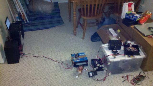
This is the whole system running, with bipolars in the LVD section. It's not the most efficient, but it definitely works as designed, just a little more wasteful than it could be...
1102-0


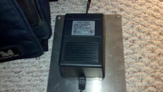
This is the brick that mimics a "hazy sunny day". I get about 1.2A out of this when I'm pulling hard, I'm afraid to push it further than that, I'm 1300 miles from home, and it's the only supply I had that has the "springyness" to tolerate being shunted. It's good for 32V @ 900mA according to the label. :)
1104-1


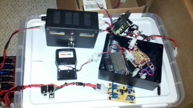
This is the power distribution system, currently a 339 based brain and a set of 4 bipolar PNP trannies driven REALLY hard to ensure they don't skimp on current. I'm wasting a bit of power here - the base resistors between the darlington sets get HOT. They're 1K @ 1W. This will be replaced with a comparable MOSFET design that uses about 1/5th the power (the juice to run the brain is on the order of 25mA @ 22V).
1106-2


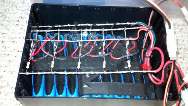
The heart of the power storage lies in a set of 10 9.6V@1Ah NiCds, set up into 5 strings of 19.2V. Total capacity for those not bothering is 19.2V@5Ah, or 96Wh. There are 4 leads going to the bank, a charge rail, a discharge rail, the meter rail, and common ground.
1108-3


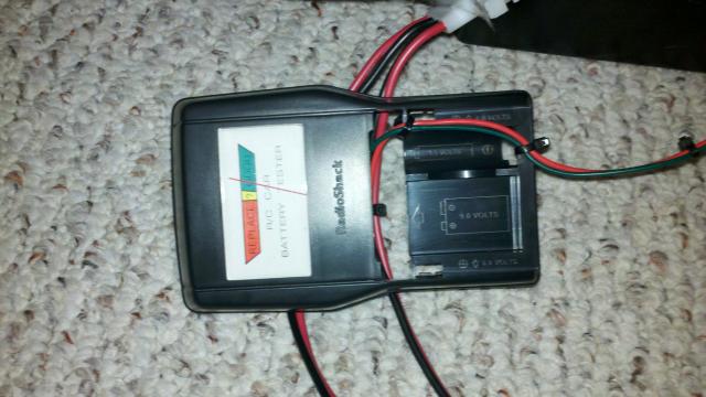
This isn't the most sophisticated "fuel gauge" for the buffer battery, but is merely intended to give an at-a-glance view - is it charged? Is there enough juice in it to run from it? Is it dying? Is it dead? That kind of thing... It's an expanded scale meter based on a couple of zeners, a few 1N4001s, a  1.5K resistor and a 1K trimmer pot. Does the job.
1110-4


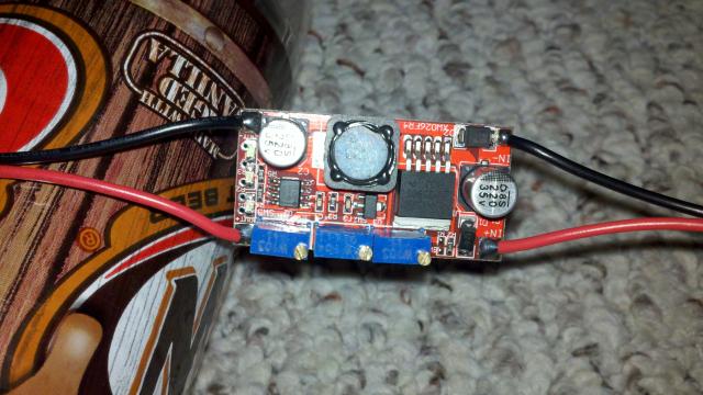
The amplifier's battery charger. A current limiting buck converter from China. Not gonna go into that now, but those that own them understand their versatility. :)
1112-5


Similarly, the laptop's power supply. Current limiting is all but disabled in this module, and is only still present to protect itself in the event of overload. It's done it's job at least once in the course of development. :/
1114-6


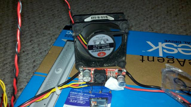
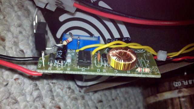
The laptop supply and it's fan controller. This is a rather significantly modified cell phone charger that is controlled by a thermistor in contact with the converter chip on the supply's buck.
1116-7


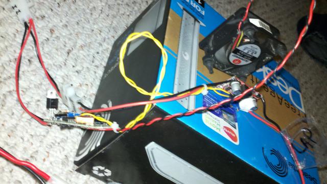
Closeup of the fan controller itself.
1118-8


More to come...
Wanted: Schrödinger's cat, dead and alive.

Offline MadScientist267

  • Impossible Condition Curator
  • Hero Member
  • *****
  • Posts: 1514
  • Karma: +44/-4
  • Rules? What rules?
Re: The System. Beta, Pics. :)
« Reply #1 on: May 09, 2012, 03:16:44 am »
Here is the shunt controller, the brain for the LVDs, and the bipolar brunt sections, a little closer.
1120-0


Another view...
1122-1


And another...
1124-2


And of course, the end result. :D
1126-3


Now to pretty it up, like the rest. >X-D

Steve
Wanted: Schrödinger's cat, dead and alive.

Offline Wolvenar

  • Senior Moderator
  • Hero Member
  • *******
  • Posts: 1474
  • Karma: +40/-0
  • Mr. Murphys pawn
Re: The System. Beta, Pics. :)
« Reply #2 on: May 09, 2012, 03:40:58 am »
How does that china built controller work for you, I have been looking at a variety of them myself for a laptop.
Trying to make power from alternative energy any which way I can.
Just to abuse what I make. (and run this site)

Offline MadScientist267

  • Impossible Condition Curator
  • Hero Member
  • *****
  • Posts: 1514
  • Karma: +44/-4
  • Rules? What rules?
Re: The System. Beta, Pics. :)
« Reply #3 on: May 09, 2012, 04:11:21 am »
They work as described, but run warm for my taste...

DanG has a set of them that run his plant LED's, the link escapes me ATM but I'm sure posts are around :)

He's got DIY sinks on his, mine are still bare. Looking into Radio Hack's version of the extruded heatsink. Found 3 of them for the bipolars, but ironically, would have done better epoxying them to the backs of the buck converters.

I'm using 3 of them right now, all spitting different voltages, and my only gripe is the low side current detection. This poses a significant problem for the lithium ions in the laptop itself. The laptop and the battery share a rock solid ground, and so all current detection has to be done high side.

Not a problem, however, I have one in place, but it's discrete, and of course eats a lot more real estate than I care for, but does the job. No, I didn't design it, just "tweaked" it a bit :)

The China modules have good line regulation, but I think a set of modest electrolytics are in order, maybe 4x1000uF on the laptop side. No low ESR additions needed as far as I can tell though... The pulsing from the brain appear regulated rock solid on the outputs, but that doesn't mean it's not there... The laptop "squawked" at least once when it should have never seen anything... ? (can't reproduce it)

Anyway, for like 20 and some change, you can get a set of 5. They're "good" to 35V, but above 28, they start to get really parasitic. ~10mA below that for the most part.

Nutshell? LEDs are sometimes whack (dim, missing, whatever)... Doesn't seem to ever affect operation. Class B, but worth it. :)

Steve
Wanted: Schrödinger's cat, dead and alive.

Offline MadScientist267

  • Impossible Condition Curator
  • Hero Member
  • *****
  • Posts: 1514
  • Karma: +44/-4
  • Rules? What rules?
Re: The System. Beta, Pics. :)
« Reply #4 on: May 09, 2012, 05:24:33 am »
BTW the version I have is rated for 3A, provided you have the heatsink (recommended above 15W). Gives up 12V/1.5A output without any problem @ 28V in, only modest heat. Above that, do something. :)

Just the copper pad on the back alone though responds well to airflow... I'm going to use 1 60mm fan to cool 4 bucks, 8 MOSFETs (which probably won't need cooling LOL) and a bipolar descrete buck converter, all running at "silent" speeds. They don't need much.

Steve
Wanted: Schrödinger's cat, dead and alive.

Offline rossw

  • Senior Moderator
  • Hero Member
  • *******
  • Posts: 879
  • Karma: +35/-0
  • Grumpy-old-Unix-Admin
Re: The System. Beta, Pics. :)
« Reply #5 on: May 09, 2012, 05:38:27 am »
I've been using these for years to operate a PTZ camera in a "PoE" situation where I carelessly ran only a single cat5 cable 80 metres, then covered the whole thing in concrete.

I run 28 volts DC up 2 pair of the cable, and one of these converters at the remote end to give me 12V at up to 2A (usually 1.2A) and it's been perfectly happy.

Offline MadScientist267

  • Impossible Condition Curator
  • Hero Member
  • *****
  • Posts: 1514
  • Karma: +44/-4
  • Rules? What rules?
Re: The System. Beta, Pics. :)
« Reply #6 on: May 09, 2012, 05:53:31 am »
They are robust, almost have to try to kill them.

Like maybe removing the "reverse polarity diode"?

Hahaha  :o ::)

Steve
Wanted: Schrödinger's cat, dead and alive.

Offline ghurd

  • Global Moderator
  • Sr. Member
  • ******
  • Posts: 442
  • Karma: +22/-0
    • GHurd Solar
Re: The System. Beta, Pics. :)
« Reply #7 on: May 09, 2012, 07:26:07 am »
Cool!

"Nutshell? LEDs are sometimes whack (dim, missing, whatever)... "
Uh, what?

G-

Offline MadScientist267

  • Impossible Condition Curator
  • Hero Member
  • *****
  • Posts: 1514
  • Karma: +44/-4
  • Rules? What rules?
Re: The System. Beta, Pics. :)
« Reply #8 on: May 09, 2012, 04:14:54 pm »
G-

There are 3 LEDs that indicate power, charge threshold, and current limiting... My understanding is that on the modules DanG received, there were one or more of them missing. And on mine, there are consistency issues with brightness etc.

But the modules themselves work fine.

Steve
Wanted: Schrödinger's cat, dead and alive.

Offline dang

  • Full Member
  • ***
  • Posts: 86
  • Karma: +5/-3
Re: The System. Beta, Pics. :)
« Reply #9 on: May 09, 2012, 11:52:39 pm »
Hey steve, I see my name mentioned?

Driving 40w label rated LEDs off two of the CC-CV circuits; two 10w LEDs in series at 23~V and 835-850ma then through a china 555 dimmer circuit.

I took them at their word and epoxied heatsinks on prior to power up - with 20w load 105-115° component temps with passive cooling.

1136-0

CC-CV units fed parallel from a 24V printer power brick and no obvious cross-talk, but did have trouble with a different 28.8V CC-CV unit drawing from same brick driving eight 3W LEDS that staggered the 555 circuit, my guess was plain over-voltage on the 555.

I'll post a narrative on the whole project sometime - the text is turning into everything I learned about LEDs last winter and is running two pages and not near finished.

"It may be that your sole purpose in life is to serve as a warning to others" - Anonymous

Offline ghurd

  • Global Moderator
  • Sr. Member
  • ******
  • Posts: 442
  • Karma: +22/-0
    • GHurd Solar
Re: The System. Beta, Pics. :)
« Reply #10 on: May 10, 2012, 08:12:22 pm »
there are consistency issues with brightness etc.

Might look for a body diode backfeeding to the LED?
If a body diode is backfeeding, it can backfeed to other things, which can create some crazy looping/amplitude/gain issues, which often result in an LED of varying brightness(when it should be ON or OFF).

If Dan's had missing LEDs, maybe yours is missing a Zener?
G-

Offline MadScientist267

  • Impossible Condition Curator
  • Hero Member
  • *****
  • Posts: 1514
  • Karma: +44/-4
  • Rules? What rules?
Re: The System. Beta, Pics. :)
« Reply #11 on: May 19, 2012, 04:33:22 am »
Sorry it took me so long to respond... been busy!  :-\

Not sure if there's anything missing or not, doesn't appear to be, but since it doesn't affect module performance, I'm probably not going to worry about it.

The LEDs on mine will probably end up being completely removed anyway, since they will all be inside a box where they won't be visible. No sense in throwing juice away in them when they can't even be seen.

My biggest problem at the moment is that because I have 2 bucks effectively daisy chained, the current draw on the one providing power to the computer is a bit excessive if the battery in the laptop is charging. The module appears to be able to handle it, but the bipolar tranny in the LVD desaturates above about 2A and ends up linear. I almost cooked it from it going into runaway, but I caught it in time (could smell the heat) and managed to save it.

I'm not really worried about it in the long run, since there will be MOSFETs there instead in the final version. But that still leaves me with the problem of 2 buck converters back to back. I'll be looking into taking the Li-Ion's buck from the 28V rail rather than 12V if I can get away with it, but that particular module is a discrete component design, and I have no idea what it's handling capabilities are in terms of input voltages. I'm a little reluctant to experiment with it too - As it is, there's minimal protection in place if something goes wrong with that part of the system. I really don't care to have a set of lithium ions go off on me!  :o

Side note: I've had at least one cell phone charger's chip violently explode shortly after connecting it to voltages that high, with no other sign of imminent failure pending (ie heat). In fact, I had just taken my finger off the chip and BANG! The workaround is to make sure I'm using MC34063 based converters. Another one failed shorted, and passed the full input virtually unimpeded to the output. Not a good scenario when a lithium pack is involved.

I'll be doing my homework either way. Can't afford not to.  :-\

Add all this together, and my next biggest hurdle is heat management in a small space. THAT should be fun...  ::)

Getting rid of as many components that waste heat though is the top priority in this for the moment. MOSFETs instead of bipolars, Schottky diodes instead of standard silicon, etc etc.

Steve
Wanted: Schrödinger's cat, dead and alive.

Offline MadScientist267

  • Impossible Condition Curator
  • Hero Member
  • *****
  • Posts: 1514
  • Karma: +44/-4
  • Rules? What rules?
Re: The System. Beta, Pics. :)
« Reply #12 on: May 28, 2012, 11:48:12 pm »
A quick post - battery is running low on the laptop and the charger is upstairs... :P

I'm making progress... The LVD is now behaving, but I REALLY need to get the bipolars replaced. How did we ever deal with that technology?!?!?

I ran it all day today, questionable sky and such, so that I could find out what it's made of.

The NiMH in the amp needs to go for sure. What a crap POS technology. Gimme back my NiCds dammit :D

Anyway, not much in terms of pics to show, for now, but I'll go on... the parts will be ordered soon and then the fun begins!

Keep you posted!

Steve
Wanted: Schrödinger's cat, dead and alive.

Offline Wolvenar

  • Senior Moderator
  • Hero Member
  • *******
  • Posts: 1474
  • Karma: +40/-0
  • Mr. Murphys pawn
Re: The System. Beta, Pics. :)
« Reply #13 on: July 30, 2012, 01:12:39 am »
have you had time to make progress on this project?
Trying to make power from alternative energy any which way I can.
Just to abuse what I make. (and run this site)

Offline MadScientist267

  • Impossible Condition Curator
  • Hero Member
  • *****
  • Posts: 1514
  • Karma: +44/-4
  • Rules? What rules?
Re: The System. Beta, Pics. :)
« Reply #14 on: August 17, 2012, 07:27:09 pm »
Well, as is known at this point by some, this one is in the can for the moment.

Many of the parts were repurposed to provide me "life support" on a little detour I've had to go on during my time here on the giant rock.

It won't be permanently dismantled, but as of this moment, I have no idea when it will resume.  :-\

Aside from the detour, one of the two panels was completely and totally destroyed during a momentary lapse of reason while ON my detour. Looks like I'll get my little wish in the end - 60W worth of panel, while able to run this system, struggled to do it on occasion, so when I do pick it all back up, I'm going to go ahead and bump the power up a bit and give me some head room. Might as well, this system uses 24V nominal at the input, and each panel I have (had) is only 12V. So I have to get a new one anyway. Why not make it all shiny and new like? :)

When I finally resume, I will pick this thread back up. Nothing in the original system has been modified beyond easy return to original design, its just a matter of being able to sit back down in front of a bench and finish it off. :-\

Steve

Wanted: Schrödinger's cat, dead and alive.