Author Topic: Doubler Hack - Fresh set of eyes please?  (Read 7643 times)

0 Members and 1 Guest are viewing this topic.

Offline MadScientist267

  • Impossible Condition Curator
  • Hero Member
  • *****
  • Posts: 1514
  • Karma: +44/-4
  • Rules? What rules?
Doubler Hack - Fresh set of eyes please?
« on: March 13, 2015, 09:23:20 pm »
Hey all...

I'm modifying an MSW inverter to get a doubled bipolar supply. It's an unusual arrangement, as they've doubled up the transformers before the rectification. This in itself isn't the problem, but I'm putting it out there to explain why the drawings are the way they are, and there is one part of the modification that may or may not become a problem.

Here's the pertinent OEM basis:

3822-0

Note both halves are configured as full wave, through current sensing resistors, and that the resistors are in parallel, tying the negative sides of the bridges together.

Now for the hiccup... I need to keep the protection circuitry intact and pacified so that current limiting etc still works, so my initial thought was to just bond one leg of each transformer (and only one, so as to minimize current sharing issues), and tap off the bridges creating a half wave doubler, like so:

3824-1

Then I realized that I was putting the existing cap in danger, not to mention tripping the protection from overvolt. So I came up with this:

3826-2

The million dollar question: Is this sane, just configured as an "isolated ladder" and all would be well, or is there anything else that isn't obvious that I may be missing before I go to do this?

Steve
Wanted: Schrödinger's cat, dead and alive.

Offline MadScientist267

  • Impossible Condition Curator
  • Hero Member
  • *****
  • Posts: 1514
  • Karma: +44/-4
  • Rules? What rules?
Re: Doubler Hack - Fresh set of eyes please?
« Reply #1 on: March 14, 2015, 01:11:05 am »
The Falstad circuit simulator seems to think it's reasonably sane...

Had to use unrealistic values for some of the components as well as pacify certain simulator requirements, but the basic concept seems to have merit:

http://tinyurl.com/ne9y3aq

For those unfamiliar with the sim, you'll need java installed and enabled. Click the "Run" button to then load and run the simulation.

Steve
Wanted: Schrödinger's cat, dead and alive.

Offline oztules

  • Forum Advisors
  • Hero Member
  • ****
  • Posts: 1177
  • Karma: +105/-8
  • Village idiot
Re: Doubler Hack - Fresh set of eyes please?
« Reply #2 on: March 14, 2015, 01:48:02 am »
I'm lost... what are you trying to achieve?

.. is it simply a series connection of the outputs to get twice the voltage, but keeping the sensor????

If so .. just series the outputs, and put the current sensor on a single leg... it is floating so you can put it where you want.... ground leg is sensible.

For a split supply... same thing do whatever you want, but keep the ground leg with Rsense... remember it is floating so  Rsense can be anywhere really... and assuming balanced outputs, then just change the R to reflect you are only measuring one current circuit... not 2

For twin output positive.... common ground... then

If you want to double it again, then a standard doubler with still the current sense in the ground leg... Rsense will get larger each time to keep the power delivered the same for the higher voltages.

.... or put another way, ignore the current sense for a while.... wire it as you would for a normal transfromer with twin output windings... when finished, determine where to put R sense, and decide what the new Resense value should be.... remembering it is floating so anywhere you want is fine.

..oztules
Flinders Island...... Australia

Offline MadScientist267

  • Impossible Condition Curator
  • Hero Member
  • *****
  • Posts: 1514
  • Karma: +44/-4
  • Rules? What rules?
Re: Doubler Hack - Fresh set of eyes please?
« Reply #3 on: March 14, 2015, 02:10:14 am »
Oztules -

I'm confined by the restraints of the original inverter design. Rsense is in the negative leg between the bridge diodes and the H bridge. I need to keep it's functionality so that the front end deals with inrush properly. I'm not trying to re-engineer the entire inverter; I need simple and reliable, and the OEM protection is multi-faceted (current/voltage limits, overtemp, etc).

This will be the first half of a HVDC link between the truck's cranking battery and the house batteries. I'm killing a few birds with this one, most notable being the lack of need for heavy cable/voltage drops and precise control over charge voltage/currents on the other end.

It only partially works using it as-is; the other half (a SMPS) goes into a state of limbo when it sees a sudden change of load (being connected upon powerup qualifies, for example) because of the flaky nature of modified sine. The SMPS requires the doubled voltage (~320VDC), as it has a doubler on-board, which of course normally doubles 120VAC. Feeding it a more stable supply should radically reduce or outright eliminate the flakiness.

That said, the only way to get the required voltages out of the MSW is clever arrangement of a doubler. To pacify it's feedback loop, I have to leave the original rectification and regulation alone. If this works, it will consist of merely two schottkies, a jumper between the two transformers, and possibly a light dummy load across the original cap to help with regulation.

So, the plan is to double it at the inverter, put some extra filtration on it, and pipe it over #14 (or so) wire to the SMPS, where it is injected directly into the HVDC front end, where of course, it gets converted down to whatever the feedback loop calls for...

Steve
Wanted: Schrödinger's cat, dead and alive.

Offline oztules

  • Forum Advisors
  • Hero Member
  • ****
  • Posts: 1177
  • Karma: +105/-8
  • Village idiot
Re: Doubler Hack - Fresh set of eyes please?
« Reply #4 on: March 14, 2015, 04:10:55 am »
I see... so you are not using the H bridge to make Ac in the msw then.

I can see you now only must have 180 dc to play with to send down the line to the remote smps....

If this is an accurate representation of what you have to play with, then I would simply throw out the Hbridge, series the secondaries of the two transformers ( they are usually driven by a common pwm signal... so in phase), rectify and send that.

Use  the series Rsense in the neg leg (higher value as current is now half .. ie cut one out), a voltage divider across the now 320vdc to get 180v to feed the pwm driver and were done.

You will then have simple rectification, and better stability, still have current control as before, and still have voltage control as before.... I have found doublers to be a much higher impedance source than I had anticipated, and lossy.
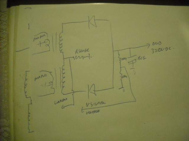
3828-0
ignore scribble on extreme left ...page under neath.... curses :-[...
Am I understanding correctly that you just want 320vdc out of the msw?? .. if so thats the strongest lowest impedance way to do it i think.

The hesitation in the smps will be an energy storage problem...... why I don't like hf inverters to begin with....I like LF where the battery is the energy storage... but,  that said, the 1/2E^2C ( energy) of the capacitor storage may need to be looked at first if you want better surge characteristics in the smps..... more caps... more storage...less ripple/cap as well ( life).... in both the msw and the smps ( assuming the fets can handle that extra umph )

It's your project though, so i will leave you alone to do as you wish... but you did ask.

Best of luck with it too... and I like your truck.


.......oztules

Ps... or you could just run the 120vac from the msw to the smps as it was designed I suppose... should not be too much loss in the Hbridge.
Flinders Island...... Australia

Offline MadScientist267

  • Impossible Condition Curator
  • Hero Member
  • *****
  • Posts: 1514
  • Karma: +44/-4
  • Rules? What rules?
Re: Doubler Hack - Fresh set of eyes please?
« Reply #5 on: March 15, 2015, 06:15:26 pm »
Oz -

Well, after much digging and tinkering with the simulator, I got some results..

There are deal-breaker problems with both your and my approach... Mine would have current sensing chasing it's tail because Rsense would only be seeing current ~50% of the time (assuming a full 50% duty cycle, which of course it's not). So that's out.

Unfortunately, because of how it's current sensing on the high voltage is implemented, your approach would circumvent the chip that's performing protection via input from Rsense. They made it so that the modified sine generator chip is the one that backs off (actually it shuts down completely) rather than the TL494 that's doing the grunt. So that's out as well.

I tried one other approach, involving the thought process triggered by your "energy storage problem" comment... I sped up the MSW generator to around 700Hz (going roughly by the graph for the chip)... This helped a little, but didn't solve the problem completely.

So, I'm basically back to square one, only with a higher frequency output from the inverter.

Next step is to add caps as you suggested, and assuming the inrush is still under control, everything will be ok... I hope  ::) :P

One thing I noticed while I was playing with the simulator was the waveforms associated with a cap across the doubler. On the SMPS, they are set up as a typical doubler, without what I would call "master" cap. In addition to stacking up the doubler caps, it would appear adding this single cap across the entire 320V would be a good idea. Your thoughts on this?

Steve
 
Wanted: Schrödinger's cat, dead and alive.

Offline MadScientist267

  • Impossible Condition Curator
  • Hero Member
  • *****
  • Posts: 1514
  • Karma: +44/-4
  • Rules? What rules?
Re: Doubler Hack - Fresh set of eyes please?
« Reply #6 on: March 15, 2015, 08:37:06 pm »
Answered my own question there... Hunted down a couple of 330uF 450V caps and put them across the doubler. Everything seems fine now, at least as far as I can do my initial tests.

Tomorrow most likely I'll try it again with the real setup and see what happens.

Steve
Wanted: Schrödinger's cat, dead and alive.

Offline oztules

  • Forum Advisors
  • Hero Member
  • ****
  • Posts: 1177
  • Karma: +105/-8
  • Village idiot
Re: Doubler Hack - Fresh set of eyes please?
« Reply #7 on: March 16, 2015, 04:41:30 pm »
You cant have too much storage..... more there is.... happier we are... and  less fluctuation there will be...


This "Unfortunately, because of how it's current sensing on the high voltage is implemented, your approach would circumvent the chip that's performing protection via input from Rsense. They made it so that the modified sine generator chip is the one that backs off (actually it shuts down completely) rather than the TL494 that's doing the grunt. So that's out as well." confuses me too.

If I read you right, the TL494 is performing the step up push pull?? ( not my choice for that application... would have expected a 3846 etc. ). To generate the HV, we don't need the msw in any way... could be dead for all we care.
If the MWS is controlling the step up from 12 to 180, then it makes little sense. I would have expected the 180vhv signal correction  and the current draw signal correction to be information relevant to the  the step up chip .....not the msw chip..... not sure what it could do with the information anyway.. except to stop?.... it can't throttle.


But it is what it is, and if it is as you appear to say, I'm bemused at the least.

..............oztules
Flinders Island...... Australia

Offline MadScientist267

  • Impossible Condition Curator
  • Hero Member
  • *****
  • Posts: 1514
  • Karma: +44/-4
  • Rules? What rules?
Re: Doubler Hack - Fresh set of eyes please?
« Reply #8 on: March 18, 2015, 09:26:16 pm »
Yep that's how they did it... Rsense essentially triggers the shutdown pin on the MSW generator. I agree, I'd rather have it back off the 494, but I suppose that would cause brown out and could be viewed as a problem as well, so they just make it cut output entirely. Probably responds a little quicker than the push pull could too, mainly because of the HV caps... but I'm just guessing there.

It is what it is... it should be fine now... in my travels to come to the end result, I also sped up the MSW to around 700Hz (roughly going by the graph in the datasheet)... the theory was less droop in the caps. It helped a little but not like adding the extra storage ;)

I still haven't gone back and checked it in a mock up situation again, but at the business end of the SMPS, with it plugged into the inverter, it handles 0 to ~25A in *now* into foglight loads without hiccuping, so should be fine. I'm working on a hall based current limiter for it now. If I ever finish it... ::)

Steve
Wanted: Schrödinger's cat, dead and alive.

Offline MadScientist267

  • Impossible Condition Curator
  • Hero Member
  • *****
  • Posts: 1514
  • Karma: +44/-4
  • Rules? What rules?
Re: Doubler Hack - Fresh set of eyes please?
« Reply #9 on: March 21, 2015, 06:25:59 pm »
Little update...

I got the hall current sense and limit implemented.. it's crude but it works. I'll be starting up a new thread and putting up some pics as soon as I get it assembled into something I can mount to wherever it all will be mounted to.

In the tests, I had it pumping somewhere in the 400W range for a short period, until the batteries were too full to help keep the whole thing loaded. It ran for 3 hours last night into some foglights I was using as a dummy load, around 250W total or better there, and no heat issues anywhere. Same thing today, going into the batteries, even though for a much shorter period because I was of course burning gas to run the test.

I've got it set to start backing off around the 250W mark for now. This covers base load + ~C/10 into the bank. It's nice to know I'll be able to increase this without any issues when the time comes ;)

Till then...

Steve
Wanted: Schrödinger's cat, dead and alive.