New Tower From Scratch (part one) Repost from fieldlines from July 15, 2010
Its summer according to the calender and the rain is bouncing of the slates and sunshine is but a distant memory! at least it is windy.
Since the start of spring I have been chomping at the bit to get started on my latest project, anew tower for the 12ft turbine but first she who must be obeyed had a long todo list for me so the last 4 weeks have been spent cutting grass, rotovating, fencing, rotovating, cutting hedges, rotovating by which time the darn grass has grown again! groan did I mention the rotovating.
but now its my time!
First job on MY todo list is a new tower for the 12 footer, I have been planing this tower since last summer and spent most of the winter at the drawing board designing it and working out the fine detail. The tower will be triangular lattice built in 10ft sections, all steel and welded construction. Initially this tower will be 50ft and will be home to my 12ft turbine but I will be adding more sections to it and building another 16ft turbine in the future. So first I ordered the steel, 6 off 1.5in od tube 20ft lengths 3 off 1.25 box section 20ft lengths, 8 off .5in re-bar the stub mast is 4in tube x 12ftI already had this pipe left over from the 16 footer. I got a good deal on the steel tube for the up-rights but could only get them already galvanised, plain steel was much more expensive go figure! no big problem just means grinding it off before welding and plenty of ventilation.
First job was to cut all the components to length, accuracy is critical if this is going to work so I clamped the cutoff saw to the bench and set up an end stop to save time measuring each component. The six 1.5in uprights were cut to exactly 10ft each and set aside.
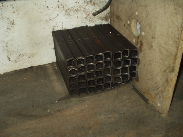
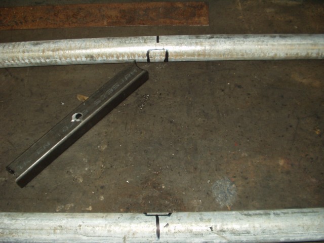
The horizontal cross-members are cut from the 1.25in box section, there are 15 cross-members in each 10ft section five on each face 60 in total and each would involve several machining steps. First step is to cut all 60 cross-members square @ 16in and then de-burr and stack them. Step two is to drill a 10mm hole through the centre of each cross-member with the vertical drill, I set up a fence and end stop on the drill table to save measuring each one and to ensure they where all identical. Step three was to cut a curve on the end of each member to match the diameter of the upright. The cut was made with a hole saw in the vertical drill and a little jig I made up to ensure each cut was identical.


The 10mm hole in each member is dropped over the 10mm stud in the jig and sits snug against the fence of the jig, the hole saw then cuts the require curve, the member is then lifted and rotated 180 degrees and cut again, this is the main purpose of the holes drilled earlier. This method again ensures they are all identical, repeat 120 times or until you fall asleep. I made 10 extra while the jig was in place in case of mishaps, a final de-bur with the grinder and we are now ready to start building. At this point I have spent Two days just cutting and pre-ping the components

Assembly begins
After a major clean up in the workshop, you wouldn’t believe the amount of swarf produced to get to this point

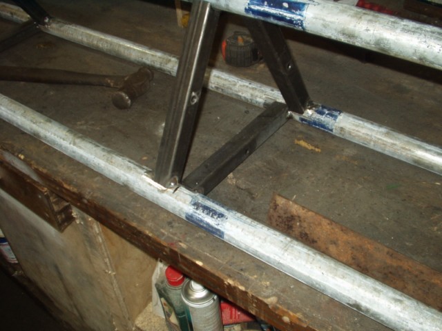
The first two up-rights are laid on the bench against a stop to keep them level and square, the five cross members are set in place and marked around, these areas are then ground clean.
Plain steel tube would have saved this step.


The members are then replaced and squared and tacked in place with a mig welder.


The third upright can now be set in place on its cross members, marked, ground clean and again tacked.
One final check that all is true and square and then welded up. I should add the cross members at each end are mitred to fit in line but the three members between are staggered. Each welded seam is double seam welded all the way around, I normally would use 1mm mig wire for a job like this but my supplier on had .8 in stock so thats what I used. It is important not to weld to much in any area at once otherwise the heat will warp and twist it like a corkscrew.
To be continued... see part two here