Author Topic: guess who bought a power jack inverter  (Read 201577 times)

0 Members and 1 Guest are viewing this topic.

Offline oztules

  • Moderator
  • Hero Member
  • *****
  • Posts: 1177
  • Karma: +105/-8
  • Village idiot
Re: guess who bought a power jack inverter
« Reply #315 on: August 26, 2015, 03:45:44 am »
Ross,
Actually thats how the PJ is supposed to work, and certainly does with the W7 powerstar transformers ( EI ) without problems. ( same boards)

I have found the PJ waits and drifts to match then pulls in the shorting relay always without a problem... but when it disconnects, it tries to re-establish 50.0hz too fast, and torroids seem to blow things up with the inrush... the lossy EI transformers in a W7 powerstar don't generate enough inrush current to bother the switchers, and so cause no problem... but gee, the big torroids can cause utter destruction.... if only they drifted back to 50.0hz like they drift in.... would be the complete package.

Thats why you need to switch the unit off before disconnect ( they say before connect too, but it is not necessary, it syncs in perfectly well on the run.

Once in sync and output is shorted to load and input, it can charge depending on the switch position of the battery types and three stage charging regimes to match.. or just run the loads in thruput mode.

In theory, if the generator has not enough to run the loads, then the unit should help it run the load ( try to keep the voltage up where it should be is all that happens i think..... I have not bothered to try it,as my generator is 7kw, so hard to find big enough load to test it out.)

.................oztules
Flinders Island...... Australia

Offline off the wall

  • Full Member
  • ***
  • Posts: 76
  • Karma: +3/-0
Re: guess who bought a power jack inverter
« Reply #316 on: August 26, 2015, 06:22:50 am »
While the PJ might synchronise, after it causing spikes on switching in the barn and blowing out LED floodlights, I haven't trusted it and in the interests of avoiding big bangs, inserting a break of a cycle or so doesn't seem to be a bad idea . . .

I kept the Neutral unearthed to avoid earth currents especially in the event of lightning as the barn is over 150 metres from the house. I'm using 5x 10mm SWA cable and from memory using 3 cores for live and 2 cores for neutral together with the external armour to beef up the neutral. It works well giving less than 10 volts drop on a 3kW load. In view of the possibility of damage to the outer insulation neutral may well become earthed and it's then that earth current complications could happen.

This is my manual switch box
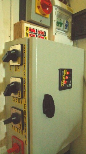

There's an ammeter monitoring the current on all three circuits switchable between solar and grid, so that if there is a particularly heavy draw I can switch back to grid, and the bottom red switch is for lights.

I've simply taken various circuits from the house and routed them through the changeover switch system.

Another of the reasons for not relying on the PJ syncing and instead giving full double pole and time delayed switching is that from the grid not all circuits are on the same phase. Whilst there are warning labels inside the box it would probably be appropriate to put more exciting labelling on the outside of the box and to make use of the lock . . .

This is the automatic box showing the type of contactors
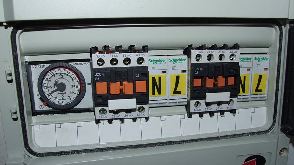
4348-1

I tried a further sequential delay putting the 2nd grid contactor energised by live from the live output of the primary contactor and the neutral of the energising coil to the output of the secondary neutral so that live would not be connected until after neutral was connected but this, however caused the earth leakage breaker to blow feeding from the solar supply.
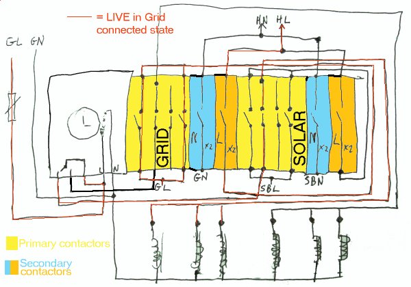
4349-2

Looking at the circuit as implemented I see that I wired the energisation of the secondary contactors with the primary contactors on account of the two systems having two different neutrals. Where Neutral was common, then the secondary contactors could be activated from the Live appearing at the switched side of the primary contactors.

In this arrangement there is less of a delay but any chance of different phases meeting has a double-barreled protection.

The delay here is only the deactivation time of the turning off contactor followed as the NC connection is restored by the activation time of the turning on time of the slowest of the three contactors.

Best wishes

OTW

Offline off the wall

  • Full Member
  • ***
  • Posts: 76
  • Karma: +3/-0
Re: guess who bought a power jack inverter
« Reply #317 on: September 03, 2015, 11:59:45 am »
I have been intrigued by a sinusoid driver board http://www.egmicro.com/download/EGS002_manual_en.pdf and on ebay these are all of around £5 or so . . .

These might be interesting as an alternate driver board for the PJ power boards . . . and  . . . one of the ebay ads suggested that it could be used for the conversion of a modified sine wave inverter also . . . which begins to be interesting if one has one lying around not doing very much . . .

Best wishes

OTW

Offline oztules

  • Moderator
  • Hero Member
  • *****
  • Posts: 1177
  • Karma: +105/-8
  • Village idiot
Re: guess who bought a power jack inverter
« Reply #318 on: September 03, 2015, 10:15:54 pm »
I was going to go this way originally, but with the PJ as cheap as they were then ( $45 for the control card then), I went this way.

Now the prices are getting high enough that I may try this board and see how it goes. The power board is simple to build, and the control card should be too.
I admit I like the PJ isolated supply for the fets, but I may give the current pump drivers a go. I have the transformars, so not much to loose I guess.

If it works, then a very powerful pure sine wave unit could be built for little money, providing the drivers can drive 6 fets in parallel.


................oztules


Flinders Island...... Australia

Offline off the wall

  • Full Member
  • ***
  • Posts: 76
  • Karma: +3/-0
Re: guess who bought a power jack inverter
« Reply #319 on: September 04, 2015, 04:42:06 am »
What intrigues me is the conversion of existing modified sine inverters to pure sine . . . ;-)

Nothing, however, in that direction can be as robust as the Power Jack units as they are.

My battery bank attracts criticism on YouTube as I use discarded but very much alive AGM batteries which I buy for no more than £15 each, wiring in multiple banks. For a 24V system I insert the link between the two series batteries as a piece of solder wire which blows at 7 amps. So safety is at the heart of the system between the cells. Groups of 10 24V batteries are wired together and connected with 6mm cable to a junction with 5 other such groups. I use Henley Block connectors combining the six wires and two connector blocks allows one to insert a solder wire fuse between the two connectors. The fuse is made up of 12 strands of solder wire twisted together and fuses at about 80 amps. 10 such banks are connected with 2x6mm cable to busbars made of one or two strips of scrap aluminium lightning conductor tape, 75mm2 and each of the banks is connected through a 100amp switch.

Using a 8000W LF inverter to which I've added the extra transformer, it's capable of supplying 20-24amps mains before the inverter trips. No doubt peaks can be much higher. Recently with dishwasher, washing machine, kettle, toaster, urn for large quantities of hot water, multiple appliances at once have caused a large draw and no doubt heavy peaks. In normal use at around 4kW none of my battery cables gets anywhere warm but the system does allow for peaks - but which have blown the fuse to a bank of batteries, cutting one out and then another and then another and then another as the availability to cope with peaks is reduced, until only one bank last week was operational and I had to go around and replace all the fuses. But the system is inherently safe and very effective.

Working with wet cell systems with heavy capacity is a very different matter.

But importantly the PJ unit has managed to exceed the fused capacity of the battery bank, which says a lot for these inverters, and I'm effectively unable to go to higher power without looking at a 48V system.

Best wishes

OTW

Offline oztules

  • Moderator
  • Hero Member
  • *****
  • Posts: 1177
  • Karma: +105/-8
  • Village idiot
Re: guess who bought a power jack inverter
« Reply #320 on: September 05, 2015, 02:23:36 am »
The only difference between a pure sine hf unit and a modified sine hf unit is the driver signal... every thing else is the same.

If you drive the h-bridge with mod drive, you get mod out, if you drive it pure sine, you get pure sine. Just need a decent filter on the output to shape the wave a bit more...... tidy it up so to speak.

 so 12v to 320vdc then bust it up into pure sine 240vac rms.... instead of modified sine 240v rms. The area under the wave form is the same, and the peak voltage attained in each cycle is the same..... just the shape is different.


.........oztules

Flinders Island...... Australia

Offline brac321

  • Newbie
  • *
  • Posts: 5
  • Karma: +2/-0
OffGrid PV: 250w black mono solar panels 6kW, 3x MorningStar MPPT 60, Oerlikon battery bank 650 Ah @ 48v, modified PJ LF-8000, DC-DC converters, etc.

Offline RFburns

  • Full Member
  • ***
  • Posts: 124
  • Karma: +10/-0
Re: guess who bought a power jack inverter
« Reply #322 on: September 08, 2015, 06:40:14 am »
This control board has already been proven to be usable about a year ago. Stu  http://www.lz2gl.com/power-inverter-3kw/  I think for those with the skills this would be the best starting point, use this to provide the driver for a 19kw PJ type output board
Get With It ,Get Over It , Get On With It ...Or Leave

Cheap and reliable wont be fast.
Cheap and fast wont be reliable.
Reliable and fast wont be cheap.

Offline oztules

  • Moderator
  • Hero Member
  • *****
  • Posts: 1177
  • Karma: +105/-8
  • Village idiot
Re: guess who bought a power jack inverter
« Reply #323 on: September 08, 2015, 03:00:16 pm »
Yes, they have done a sterling effort there.... not how I would have done it either.

Not sure of their thinking , but they made it work. Would like to have seen a scope of the driver signal on the cro. ( at the gate source resistor). It  looks a bit over the top for the drivers, and I'm not sure if it is warranted..... or even better than direct drive from the drivers...... I seem to use loads more copper... wondering at the heat in those windings at power for too long.

It is an interesting approach. If the switching is vastly improved ( and it was good just with single bipolar totems), then it may make up for their high Rds on. Theirs is 10 times higher than the 4110's... so 10 times the losses, and less of them... more losses.... at least they have half the input capacitance.


So I think they have done brilliantly... but thinking the Chinese PJ can show them a few things too.

 If I was to test this way, I would use a pj power board driven direct..with feedback.......... and then test a pair of isolated power supplies and totems or opto's for the high side and see if there is any advantage in not using the boards output as is.

There are a few (EG8010)  on my bench from a few years ago... have not touched them as yet..... struggling to see why at the present..... as I have too many inverters laying around from experiments so far. ... may have to try it out of curiosity one day..... but not like them.

But the PJ boards are pricing themselves much higher now .... 45 dollar boards are now near 100, and power cards are expensive too now.... but gee they are still good value..... used to be $179 for complete board set........ sigh....


..........oztules
Flinders Island...... Australia

Offline RFburns

  • Full Member
  • ***
  • Posts: 124
  • Karma: +10/-0
Re: guess who bought a power jack inverter
« Reply #324 on: September 08, 2015, 03:19:54 pm »
i would say their thinking would be akin to mine in that this design is similar in some ways to a class E AM transmitter this may provide some insight to various methods of drive for Fets http://www.classeradio.com/  at high efficiency and while being used to produce AM switching is switching and you may find something of interest here  . Stu
Get With It ,Get Over It , Get On With It ...Or Leave

Cheap and reliable wont be fast.
Cheap and fast wont be reliable.
Reliable and fast wont be cheap.

Offline off the wall

  • Full Member
  • ***
  • Posts: 76
  • Karma: +3/-0
Re: guess who bought a power jack inverter
« Reply #325 on: September 14, 2015, 08:51:09 am »
I have set up a small solar shed installation for an outside workshop. Three scrap solar panels are mounted vertically on the south wall and keep the batteries topped up for occasional use. I've connected a 3kW PJ inverter. The standby current used to be 3Amps and since using 4 turns on the E cores it's down to 400mA. But I have a problem. The two E cores are chattering together under load: what's the best way of stopping the vibration?

I thought I could get away with fitting the inductor inside the case but it's about 1/2 inch too thick :-(

Best wishes

OTW

Offline brac321

  • Newbie
  • *
  • Posts: 5
  • Karma: +2/-0
Re: guess who bought a power jack inverter
« Reply #326 on: September 14, 2015, 10:56:35 am »
Hi OTW,

I've experimented with E cores too, but ended on a ferite ring core 101 x 15 mm http://atv.hamradio.si/photo_album/_projects_/Photo_Voltaic/PV-2015/slides/IMG_9032.html

Winding 14 turns of a 25 mm2 welding cable on will do the job. Even better if you get 16 turns on. On a 8kW 48/230v PJ the standby current with 14 turns drops down to 310 mA (14,4W)   :)

Mike
OffGrid PV: 250w black mono solar panels 6kW, 3x MorningStar MPPT 60, Oerlikon battery bank 650 Ah @ 48v, modified PJ LF-8000, DC-DC converters, etc.

Offline oztules

  • Moderator
  • Hero Member
  • *****
  • Posts: 1177
  • Karma: +105/-8
  • Village idiot
Re: guess who bought a power jack inverter
« Reply #327 on: September 14, 2015, 12:28:38 pm »
Super glue the cores together. you must stop all mechanical movement possible between the cores.... super glue does this if applied properly... ....if it still whines, then you still have movement some where..... some how...... try again.


Mike, good job on the idle currents.... you may get more turns or thicker wire ( much better) if you strip the casing off and use heat shrink... 25mmsq is a bit light for my taste if your going to push it hard for long.... or are you using the original transformers,,, or maybe parallel up would be best... nice looking solution.

..............oztules
Flinders Island...... Australia

Offline brac321

  • Newbie
  • *
  • Posts: 5
  • Karma: +2/-0
Re: guess who bought a power jack inverter
« Reply #328 on: October 01, 2015, 05:50:55 am »
you may get more turns or thicker wire ( much better) if you strip the casing off and use heat shrink... 25mmsq is a bit light for my taste if your going to push it hard for long.... or are you using the original transformers,,, or maybe parallel up would be best... nice looking solution.

Yes, I know. Have tested it up to 5kW and coil became a bit hot after few hours...  Normally there is only up to 3kW power every day on it (heat pump or washing machine). 25 mm2 is just a temporary solution, it's still inside the original - to small Chinese Aluminum shell. Yes, transformers are in the moment original.

Good idea about using heat shrink ...

Anyhow, few days ago I got on eBay from one German a bit larger transformer, sizing 23 x 14 cm. Will unwind the secondary and put mine on.

What about original metal/sheet shields around PJ transformers, what are they for?
I guess, they put them only to protect winding...  and they prevent more efficient cooling  :-\


OffGrid PV: 250w black mono solar panels 6kW, 3x MorningStar MPPT 60, Oerlikon battery bank 650 Ah @ 48v, modified PJ LF-8000, DC-DC converters, etc.

Offline RFburns

  • Full Member
  • ***
  • Posts: 124
  • Karma: +10/-0
Re: guess who bought a power jack inverter
« Reply #329 on: October 09, 2015, 10:49:34 pm »
I would be thinking the metal sheilding is to reduce the RFI produced as this potentially could produce problem's with the switching frequency
Get With It ,Get Over It , Get On With It ...Or Leave

Cheap and reliable wont be fast.
Cheap and fast wont be reliable.
Reliable and fast wont be cheap.