Author Topic: guess who bought a power jack inverter  (Read 203232 times)

0 Members and 1 Guest are viewing this topic.

Offline oztules

  • Moderator
  • Hero Member
  • *****
  • Posts: 1177
  • Karma: +105/-8
  • Village idiot
Re: guess who bought a power jack inverter
« Reply #300 on: July 10, 2015, 03:26:31 am »
The raised board are a later addition/change, but essentially electrically identical, but for bigger caps and some through hole components that were surface mount before .... the totems and opto's are the same ( or equivalent).


...............oztules
Flinders Island...... Australia

Offline hurvayz

  • Newbie
  • *
  • Posts: 6
  • Karma: +0/-0
Re: guess who bought a power jack inverter
« Reply #301 on: July 10, 2015, 03:53:35 am »
 :)
Ok
Problem is, i cannot find this fet 2sc2873 in shop.
Can i give another part? in to92 dimensions.
thnks

Offline oztules

  • Moderator
  • Hero Member
  • *****
  • Posts: 1177
  • Karma: +105/-8
  • Village idiot
Re: guess who bought a power jack inverter
« Reply #302 on: July 10, 2015, 02:48:05 pm »
http://www.ebay.com.au/itm/10PCS-2SC2873-Y-Encapsulation-SOT-89-/381095888269?pt=LH_DefaultDomain_0&hash=item58bb15c58d

TO92 will be very hard on the tracks. Stay with the original if you can.
any 2Amp 50v npn  hfe>130 will do it I guess.

eg 2sa1020 and 2sc2655 will do for the totems.

If you want to stop it from burning things again, perhaps some series micro fuses and a transient supressor/diode across the totem outputs.That way if you blow the fets in testing, it won't destroy your hard work rebuilding the drivers.


.............oztules
Flinders Island...... Australia

Offline hurvayz

  • Newbie
  • *
  • Posts: 6
  • Karma: +0/-0
Re: guess who bought a power jack inverter
« Reply #303 on: July 11, 2015, 02:44:08 am »
OK thanks.

Offline hurvayz

  • Newbie
  • *
  • Posts: 6
  • Karma: +0/-0
Re: guess who bought a power jack inverter
« Reply #304 on: July 13, 2015, 04:13:03 pm »
Hey.
So the third attempt to defect again.
They were used in the driver transistors SS8050.
Inverter nicely buttoned and had a nice sine wave, consumption at idle as before the first puncture 0,8A
When taking 50W no problem.
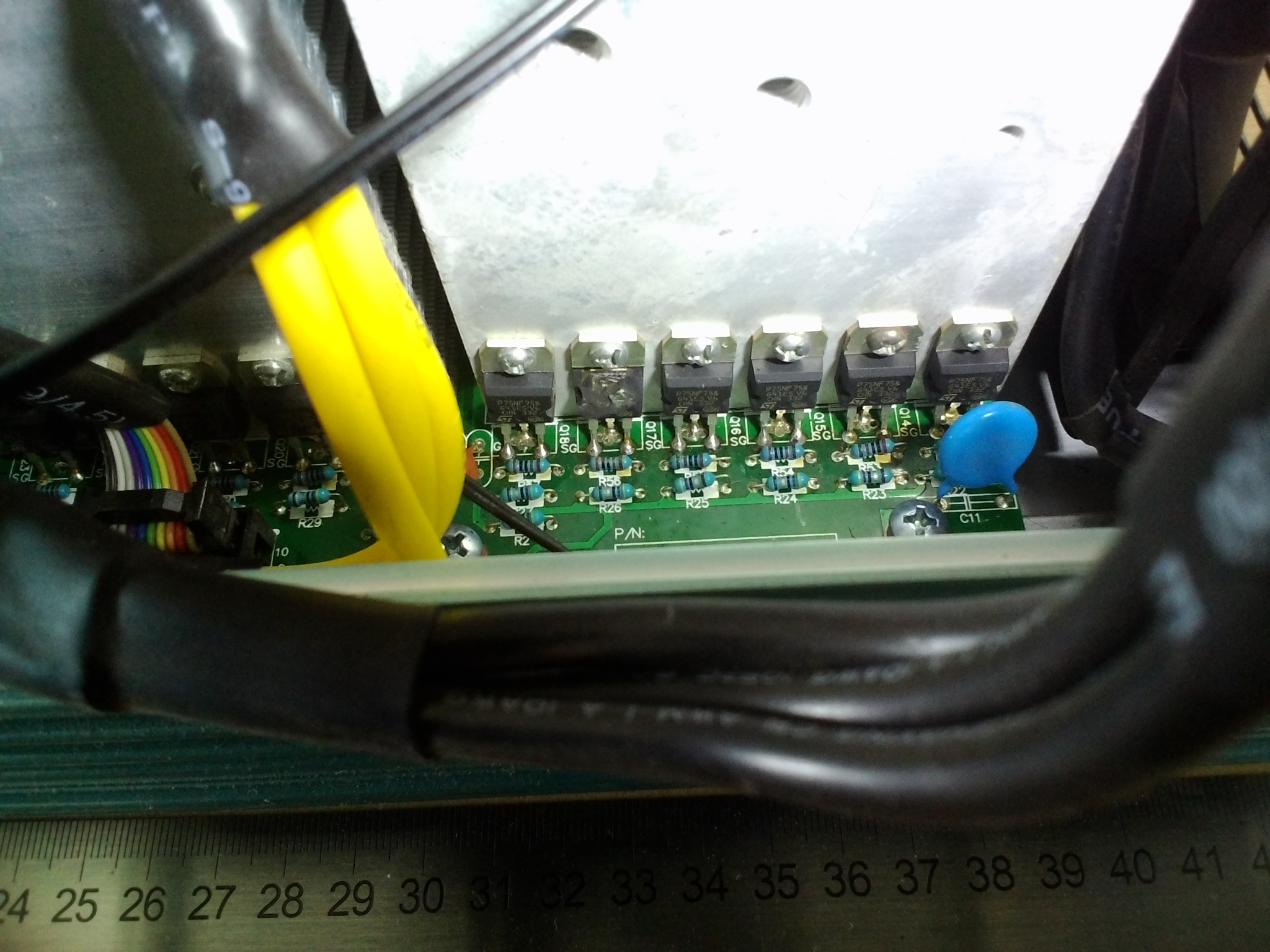
500W under load again defect, the entire left half of the mosfet KO
What might be the problem? I've been baffled.
Thanks
 :'(

Offline oztules

  • Moderator
  • Hero Member
  • *****
  • Posts: 1177
  • Karma: +105/-8
  • Village idiot
Re: guess who bought a power jack inverter
« Reply #305 on: July 13, 2015, 05:08:58 pm »
Flinders Island...... Australia

Offline hurvayz

  • Newbie
  • *
  • Posts: 6
  • Karma: +0/-0
Re: guess who bought a power jack inverter
« Reply #306 on: July 14, 2015, 12:03:29 am »
s8550 for PNP

Offline OTG

  • Jr. Member
  • **
  • Posts: 42
  • Karma: +2/-0
Re: guess who bought a power jack inverter
« Reply #307 on: July 26, 2015, 11:37:07 pm »
Hi All,

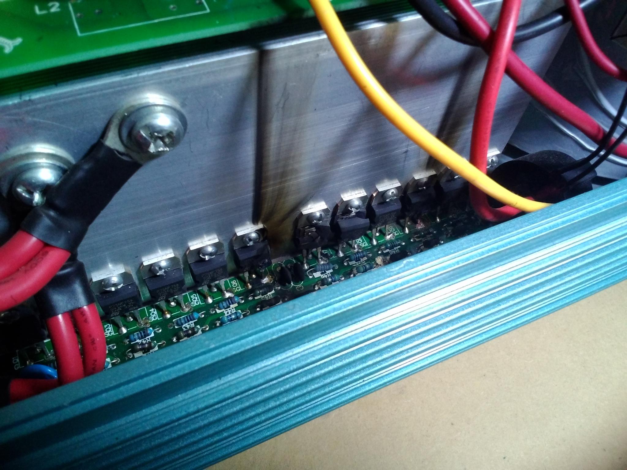
The Better-Half had the electric lawn mower out the other day and 15mins later came to me in the garden to advise it (24v 5000W LF) had suddenly stopped and there was a puff of smoke and a burnt smell coming from the inverter...  ??? The pictures say it all, 15 months after I got it...  :(

4229-04231-1

It looks to me like that middle fet on the + side of the Main Board burned up and popped the 2 fets to the right, as well as the 1 fet on the - side.

The mower is 1100W and admittedly at start-up it would invoke the overload alarm for one single beep and then power on without issue. All other appliances (water pump, kettle, mulcher, Laptops, power tools, etc) always worked without issue. The inverter only receives fairly limited part-time use, manually switched on/off as needed, because lights, fridge/freezer, and small appliances (Laptops, Radios, etc) all run direct from the DC charge controller.

So any ideas out there what went wrong? I'm admittedly ignorant of proper inverter etiquette... e.g. could cold-starting it at 6:30am most mornings to boil my tea have contributed to it's early demise? I recall you mentioning OZ that putting fuses (like NT00/NT1?) between your inverter/batteries can help save your fets under certain circumstances too. Admittedly I only have 2 x high voltage DC isolator switches on the positive side. I'm using 4 gauge power cable on all 4 terminals. Pro's/Con's of using 2 vs 4 terminals?

ANY advice that would help me to prevent future such incidents would be  greatly appreciated!!!

Thanks to OTW, I'm now in touch with Cher for replacement boards. She's confirming if the Main Board with detachable fets will work in my inverter (would make future repairs quicker/easier/cheaper). I notice there's about 3 wires to solder to the Control Board, beyond that, anything I should look out for/do specifically?

Plus I'm finally biting the bullet and ordering an 8000W unit while I'm at it. I've asked Cher to ensure I get a good'un (i.e. 2 x 5000W Toroid's - thanks OZ  :) ). Is there anything else I should be looking out for/requesting?  Can anybody confirm if the current boards do indeed have a better/lower idle current than the old boards? And have they also fixed/raised the high voltage alarm level?

PS: So the 5000W is now destined for the bore and I'll wire a 24v Timer into the on/off switch so it pumps autogomagically without me having to make a trip down the hill...  8)

Thanks all!

Offline oztules

  • Moderator
  • Hero Member
  • *****
  • Posts: 1177
  • Karma: +105/-8
  • Village idiot
Re: guess who bought a power jack inverter
« Reply #308 on: July 27, 2015, 05:27:27 am »
A fuse.... will only help stop board burning... and possibly the totems if it goes fast enough. I only want it to stop te totems burning the board. This is when the fets fail, and the 30v ( 60 in my case)can go back through the gate resistors, and burn up the transistors on the totem. If the fuse won't blow because the cascade is too slow, then there is a good chance that the 60v will continue back through the 10 pin wiring, and cook the circuit board under them.

It won't stop fets blowing i wouldn't think. I have not had them blow for no reason that I have not caused... so can't really comment on why they decided to go. They gave a huge margin for o/load with the 4110 fets in the 48v units, not sure of the 24v ones...... but o/load is very unlikely to kill them... more probably something to do with voltage spikes from loose connection in the battery line, or terminal connections in the inverter to the heat sinks.... or even the 10 pin ribbon is loose.

OTW has a lot more info than me on what PJ may be doing now, it is some time since I bought one now... but I believe the idle current has been addressed, and the last 15kw 48v board I got seems to have no bad habits of any kind re... the over voltage from the pulse charger... or anything else really.

I suspect you will need both boards replaced unless you have a good soldering iron...... then totems, opto's, fets and resistors on the fet board (50r ones) will need replacing at the least.....probably should be enough.... but why it blew?????? look for loose somewhere....

The 24v ones may not burn up the boards under the totems, but the 48v ones sure do.

for 24v units, use all 4 terminals if you have the opportunity..... I don't like 24v at over 1-2kw, as the currents get out of hand too quickly.


.................oztules
Flinders Island...... Australia

Offline MadScientist267

  • Impossible Condition Curator
  • Hero Member
  • *****
  • Posts: 1514
  • Karma: +44/-4
  • Rules? What rules?
Re: guess who bought a power jack inverter
« Reply #309 on: August 01, 2015, 03:18:22 am »
Quote
It looks to me like that middle fet on the + side of the Main Board burned up and popped the 2 fets to the right, as well as the 1 fet on the - side.

OTG - Go after the set, not just the 3 that are obvious. You're likely to find others have locked up, and likewise, there will be some that may still bench ok but have sustained damage. Be right back in there at the first sign of the next transient etc yada. No fun.

It may look like a real PITA changing them all out, but while you've got it torn down is the time. I'm sure I'm not the only one that's tried to skimp on this and been bit by it :-\

Steve
Wanted: Schrödinger's cat, dead and alive.

Offline herbnz

  • Newbie
  • *
  • Posts: 5
  • Karma: +0/-0
Re: guess who bought a power jack inverter
« Reply #310 on: August 22, 2015, 09:36:14 pm »
Hi Just been reading this. Notice mention Of the adding of a choke to the Dc input to transformer reduced standby current significantly. I was recently lead a merry dance on a inverter unit that showed high standby current on my clip on dc meter even moving coil meters showed less but high resorted to moving iron meter different story. Cannot remember figures now but it was extremely bad filtering allowing radiation. Could get readings without clipping over the lead even  . Have since seen this on a number of cheap inverters.

Herb

Offline oztules

  • Moderator
  • Hero Member
  • *****
  • Posts: 1177
  • Karma: +105/-8
  • Village idiot
Re: guess who bought a power jack inverter
« Reply #311 on: August 22, 2015, 10:19:41 pm »
Very nice to hear your still alive Herb.

Yes, the tiny filter seems to make a huge difference, much more than it should... but it is a real difference, as even the transformers run much cooler. I use analogue meters because of spurious reporting from digital stuff any where near pwm power stages.... and clip ons are only for rough guidance  I think in this scenario.

Nice to hear from you

...............oztules
Flinders Island...... Australia

Offline off the wall

  • Full Member
  • ***
  • Posts: 76
  • Karma: +3/-0
Re: guess who bought a power jack inverter
« Reply #312 on: August 26, 2015, 01:14:18 am »
Perhaps this should be the subject of another thread but finding that my 8000W inverter enhanced by another transformer from a 5000W unit provides power so reliably that I don't have to think about it most of the time the challenge became to construct a timeswitch that could choose power either from the Grid for off peak cheap electricity or the solar battery bank the rest of the time.

I'm running the solar system without an earthed neutral, so requiring double pole isolation in changing over between grid and solar.

I found using a timeswitch to apply grid to the inverter to run the inverter as a UPS system that large voltage spikes were produced and it blew two LED floodlights in a couple of months. For this reason I have gone out of my way, bringing the supply to the house rather than merely the barn and workshop, to use rotary manual double pole changeover switches with a very clear off position. These ensure that at no time is there connectivity between grid power and inverter power. In changing over, however, modems and printers would go into a reset routine every time.

So the challenge for a switch was interesting.

I used a quadruple pole contactor with 2NO and 2NC contacts rated at 20amps, and, running at a maximum 30 amps ran the lives in parallel through the 2NO contacts. I used two identical sets of units, one for connecting to grid and one for connecting to inverter. I used one of the two NC contacts to feed energising current to the other contactor. This means that one contactor cannot be operated until the other contactor is clearly in OFF mode. I then took the live from this contactor to feed the energising signal to two more contactors, one for live and one for neutral. This means that both live and neutral cannot be connected until the 4pole contactor is firmly ON and the other supply firmly disconnected by their similar units.

The system works well and on account of giving a specific time delay of only one or two cycles presents any phase difference not as a wild jump but simply as a glitch of a missing cycle or two.

Upon connection, a contactor isn't going to move until the cycle is well above zero. When that connects in will be subject to a mechanical delay. That then feeds energising current to the two contactors for Live and Neutral and likewise these won't move until the next maximum. I'm guessing therefore that there will be a two peak delay between initial energisation and the connexion resulting. Meanwhile that process won't have been initiated before the other unit has not only disconnected from its phase but made the NC contact to enable and initialise the contactor of the new phase to be connected. In doing so the live of the previous phase will have been disconnected for certain, leaving their following contactors for L and N to break connexion in their own time.

The arrangement works as regular as clockwork, literally and at 12.30 GMT and 7.30 GMT a mechanical clonk announces the changeover without any mains equipment showing any signs of noticing.

Best wishes

OTW

Offline ClockmanFrance

  • Full Member
  • ***
  • Posts: 171
  • Karma: +11/-0
Re: guess who bought a power jack inverter
« Reply #313 on: August 26, 2015, 02:16:01 am »
Thanks OTW.

Your contactor double pole change over arrangement is something I have been considering. Now that you have done something solid, I will obtain the necessary bits.

 Here in France I can then utilise the Cheap night tarrif, as EDF give you a 2a relay contactor switch, so no time switch required.

Photo, At present I have manual double pole change over switches, centre position is OFF. I am pretty quick with them and not a lot of household appliances are disturbed, but the young boys Play Station always freaks out.


Offline rossw

  • Senior Moderator
  • Hero Member
  • *******
  • Posts: 879
  • Karma: +35/-0
  • Grumpy-old-Unix-Admin
Re: guess who bought a power jack inverter
« Reply #314 on: August 26, 2015, 02:30:36 am »
I have a completely different inverter system to you - one that's designed to be generator interactive (and/or grid interactive).
When the generator/grid input is connected, the inverter see it is there, but does nothing with it initially. Once it's happy it's stable, it matches the inverter voltage to the generator/grid voltage, matches the inverter frequency to the generator/grid frequency and then drifts the inverter phase to match the generator/grid phase. When all three are the same (or near enough), it pulls in a hefty contactor and bridges the inverter output, the generator/grid input, and the load - all together.

This works completely flawlessly - both changing to and from generator/grid, I've had no glitches in over 10 years.

It would be nice if it were "easy" to build something similar for your application.
Assuming the inverter frequency is within 0.1Hz (and I would expect it to be!), there may well be enough phase drift (but still slowly enough) for a simple phase comparator made from a couple of opamps to detect when they're synchronised and pull in a contactor.

(That doesn't address the isolated neutral, which would be illegal in my country anyway)