Author Topic: My misc jaunx  (Read 10130 times)

0 Members and 1 Guest are viewing this topic.

Offline MadScientist267

  • Impossible Condition Curator
  • Hero Member
  • *****
  • Posts: 1514
  • Karma: +44/-4
  • Rules? What rules?
My misc jaunx
« on: December 05, 2012, 11:07:14 pm »
Just a quick place to throw things to get ideas from A to B, schematics in the making, etc. Nothing special.

First one: Heater element control for the van... This works, but is hell on the contacts of RLY 1. Working on a solid state solution instead.

1694-0
Wanted: Schrödinger's cat, dead and alive.

Offline MadScientist267

  • Impossible Condition Curator
  • Hero Member
  • *****
  • Posts: 1514
  • Karma: +44/-4
  • Rules? What rules?
Re: My misc jaunx
« Reply #1 on: December 06, 2012, 12:28:31 am »
Ok, Ross found a flaw with the layout above, involving backfeed through the dimmer. It didn't really prove useful in its original purpose anyway, as I ran it wide open all the time regardless, so I'm getting rid of it...

The next revision looks like this, same key as above...

1696-0

EDIT - The fix for the arcing in RLY 1 was a 0.22uF 600V cap across the common and normally open contacts on each of the two sets. This rendered the circuit below unnecessary, so no further development on it took place. Anyone, feel free to do anything you wish with it, just keep in mind it is conceptual, and was never built or tested. :)

Steve
Wanted: Schrödinger's cat, dead and alive.

Offline MadScientist267

  • Impossible Condition Curator
  • Hero Member
  • *****
  • Posts: 1514
  • Karma: +44/-4
  • Rules? What rules?
Re: My misc jaunx
« Reply #2 on: December 06, 2012, 01:31:20 am »
Ok, now the conceptual solid state replacement for RLY 1... Window comparator fed by RC network to prevent shoot-through.....

1698-0
Wanted: Schrödinger's cat, dead and alive.

Offline MadScientist267

  • Impossible Condition Curator
  • Hero Member
  • *****
  • Posts: 1514
  • Karma: +44/-4
  • Rules? What rules?
Re: My misc jaunx
« Reply #3 on: December 18, 2012, 04:23:21 pm »
Conceptual catalytic propane heater valve control mechanism.

Shown in "on" mode (shutdown solenoid engaged), on idle (state unit would be in when thermostat is "satisfied".

For full power mode, bottom solenoid pulls in, to the limits prescribed by the full power adjustment stop. The solenoid pulls on the control arm yoke, a set of 2 plates held together by a set of 4 screws, so as to pull evenly on the idle screw, which pulls the control arm in to open the valve.

On idle, the valve is held open to the degree prescribed by the idle adjust screw, against anchoring provided by the idle stop.

In the event of a fault condition, power loss, or the unit is turned off, the shutdown solenoid releases, preventing any pressure from being applied to the valve regardless of the other solenoids state. The shutdown solenoid would be held engaged by a microswitch that its armature keeps the contacts closed when the coil is energized. The switch would be in series with the coil, so if the solenoid is released for any reason (fault, power loss, heater turned off), the solenoid will remain disengaged until manually re-engaged by a momentary push button switch (likely incorporated with a spark ignition system).

The diagram:

1823-0

Steve
Wanted: Schrödinger's cat, dead and alive.

Offline MadScientist267

  • Impossible Condition Curator
  • Hero Member
  • *****
  • Posts: 1514
  • Karma: +44/-4
  • Rules? What rules?
Re: My misc jaunx
« Reply #4 on: December 18, 2012, 06:20:00 pm »
The entire reason I decided catalytic instead of open flame:

1825-0

This was an attempt to light the torch from the catalyst on the Coleman cat heater.

The torch at no point developed a flame, the propane simply hit the surface of the catalyst and was oxidized, increasing the local temperature of the catalyst.

Not much chance of this thing igniting ANY gas, and with the undertemp detection (for sensing if the temp of the catalyst is too low to burn the propane completely), chances of a problem are reduced to a flammable solid of some kind coming in direct contact with the top of the heater. There will be tip over protection for that.

Steve


Wanted: Schrödinger's cat, dead and alive.

Offline MadScientist267

  • Impossible Condition Curator
  • Hero Member
  • *****
  • Posts: 1514
  • Karma: +44/-4
  • Rules? What rules?
Re: My misc jaunx
« Reply #5 on: December 18, 2012, 10:03:41 pm »
Control schematic for solenoid valve control of above heater valve, complete with safety mechanisms. I left out the overtemp protection, as there was no such thing in the original, and the only reason I was interested in implementing it to start with was for gas conservation, which can be handled mechanically.

This has undertemp cutoff, with tipover protection, and a manual reset button that is held for a few seconds at cold start, which holds both solenoids engaged in order to provide the appropriate conditions for ignition. The button needs to be held until the green LED lights, indicating that the temp of the catalyst is above the minimum threshold and the unit will then operate on its own.

The ball hanging from the spring in the grounded V-shaped cup is for tipping/bumping detection, and shorts the baseof the TIP120 to ground, turning the transistor off, releasing the safety solenoid, sending the u unit into lockout until human intervention resets it for continued operation.

The schematic:

1827-0

Steve
Wanted: Schrödinger's cat, dead and alive.

Offline MadScientist267

  • Impossible Condition Curator
  • Hero Member
  • *****
  • Posts: 1514
  • Karma: +44/-4
  • Rules? What rules?
Re: My misc jaunx
« Reply #6 on: December 20, 2012, 05:25:47 pm »
Thermistor and thermocouple reading from ~ same spot on catalyst...

Left meter is degrees 219F, right meter is resistance of thermister, 3.38k ohms.

This is approximately where low cutoff and shutdown would outfit.

Below that is a closeup of how the thermocouple and thermister are positioned for detection.

1829-0


1831-1


Steve

Wanted: Schrödinger's cat, dead and alive.

Offline MadScientist267

  • Impossible Condition Curator
  • Hero Member
  • *****
  • Posts: 1514
  • Karma: +44/-4
  • Rules? What rules?
Re: My misc jaunx
« Reply #7 on: December 20, 2012, 05:47:44 pm »
And here it is running at what will be designated "full power"...

1833-0

614F, 553R


1835-1

See? No crispy critters here! ;)

Steve
Wanted: Schrödinger's cat, dead and alive.

Offline MadScientist267

  • Impossible Condition Curator
  • Hero Member
  • *****
  • Posts: 1514
  • Karma: +44/-4
  • Rules? What rules?
Re: My misc jaunx
« Reply #8 on: December 22, 2012, 10:32:51 pm »
Here is the controller.

After a half day chasing my tail over a bad op amp chip, I had to scrap the original board and find another way.

My second attempt involved trying to utilize the ZM chip in the infamous Ghurd controller (one that didn't quite make it to "dump controller" status). While tinkering with the controller, I realized that Ghurd thinks WAY outside the box, and what he has done with that IC is simply genius. It wasn't intended to do what he has very successfully made it do in the dump controller, but he managed to exploit very well in his design.

I wasn't as lucky with the ZM chip for my application, but the idea of using a chip for something completely different than it's original intended purpose inspired me to think a little deeper.

What I came up with works very well, and is about as unorthodox as it gets. I used an LM2575T adjustable switching power supply control chip to acquire my "trip" sequence. This is a 5 pin device in a TO-220 case, and has supply voltage, output, ground, feedback, and an "on/off" pin.

The exploit is in the on/off pin. It has a very sharply defined trip point along with just a touch of hysteresis. The thermister is tied in with this pin as part of a voltage divider. As the thermister crosses the internal threshold (about 1.4V), the chip comes to life/shuts down. The only other requirement to make it do what I needed it too do was to ground the feedback pin. This causes the chip to go full throttle to bring the output to the positive rail, as the original use for the chip uses the feedback pin to vary the duty cycle as necessary to regulate the output voltage. Keeping this pin low tricks it into 100% duty.

So, you have a voltage controlled switch essentially.

The output from this chip drives the gates of the MOSFETs, which in turn control the solenoids.

The tip/bump sensor is a normally open "switch" that closes momentarily (or longer) depending on if the unit is bumped or tipped over, respectively. This shorts the gate of the safety control MOSFET to ground, causing the solenoid to release.

The lockout switch is held closed by the safety solenoid, and if the solenoid lets go for any reason, these contacts will remain open, interrupting the gate control signals for the MOSFETs, keeping the unit locked in shutdown mode.

The minimum catalyst temperature is set by a pot on the board, and can be varied between about 180F and 260F. This setting corresponds to the lowest temperature the catalyst can go down to and still reliably go to full power when the valve is suddenly opened up full throttle. This temp was determined by trial and error, cycling the temperature several times and letting it sit and stabilize at progressively lower and lower temperatures until opening the valve completely resulted in the emission of odorant in the "exhaust", indicating incomplete combustion. When finally put into use, this threshold will be set about 30F higher than the temp where reignition failure was noticed, for an extra safety margin.

The 5V reference pilot just indicates that the stable reference chip is operating.

The catalyst thermistor is the sensor at the edge of the heaters guard which senses the temperature of the catalyst.

12V power in, pretty self explanatory. Just plug it in to any one of the many 12V sources in the van and go.

The solenoid connectors go to the safety and "full throttle" solenoids. When the full throttle solenoid is disengaged but the safety solenoid is engaged, the valve is held at the "idle" position by set screws adjusted to hold the catalyst temp just above the low temp cutoff threshold. Likewise, maximum catalyst temp is adjusted by a set screw that limits the degree that the valve can be opened. This isn't a safety function, it is purely an economic feature. Above a certain level, the temp doesn't rise much higher, but the hissing in the valve progressively increases. The result is propane that doesn't get turned into heat energy (and may pose a potentially dangerous situation if more gas comes through the valve than the catalyst can process). Not likely, but just in case, I'm limiting it for both reasons.

The power switch... It's... a... power switch :)

The control board has 3 LEDs and a momentary push button switch. The button is for resetting a fault condition caused by bumping/tipping the unit if the heater is "righted" and the button pushed before the catalyst temp drops below cutoff. During this time, a piezo beeper alarms with a steady tone until either reset is pressed, or low temp cutoff results in full shutdown. During/after any fault condition, the red LED is lit. The audible alarm is only on if the heater can simply be "reset".

From cold start or fault condition resulting in/from low catalyst temp shutdown, the button is pushed and held, then after several seconds an ignition attempt should be made (lighter, etc). There is a brief "flash" when the unit ignites, followed by immediate catalytic action. The button is held until the green LED illuminates, at which point the controller will keep the safety solenoid engaged.

Any time the button is pressed, the detection circuitry is bypassed and both solenoids engaged (to facilitate ignition).

The yellow LED on the control board indicates the "full power" solenoid is engaged.

I have partial schematics scattered throughout, I'll compile them into a single drawing and put that up soon.
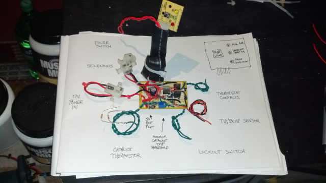
1837-0

Steve
Wanted: Schrödinger's cat, dead and alive.

Offline madlabs

  • Full Member
  • ***
  • Posts: 113
  • Karma: +7/-0
    • Chief Bottle Washer
Re: My misc jaunx
« Reply #9 on: December 24, 2012, 10:02:24 am »
Steve,

You are still a mad-man. But I am glad that you are using your mad skills to add some safety to your crazy heater! No crispy critters! No crispy ones but did have a CO poisoning the other day. Don't run the generator in the garage with the outside door closed and the inside one open! Duh!

Jonathan
Some people are like a Slinky - not really good for anything, but you still can't help but smile when you shove them down the stairs.

Offline MadScientist267

  • Impossible Condition Curator
  • Hero Member
  • *****
  • Posts: 1514
  • Karma: +44/-4
  • Rules? What rules?
Re: My misc jaunx
« Reply #10 on: December 25, 2012, 12:40:21 am »
LOL you know it. :P

I'm striving for simplicity as much as possible with this, less parts to fail means less likelihood of failure.

There are always going to be those "weakest links", and I haven't found where it is on this.

Hope I never do.

If I designed it right, and I believe I have (at least in the electronics so far), there should never be an issue. I occasionally tempt fate, sometimes with devastating consequences, but after going through and experiencing what I have in the last several months, my life is no longer a gamble on that list.

I did sacrifice just a touch of simplicity in exchange for a much greater return in ease of mind. I went about as ape$#!+ as one can go with freewheeling diodes. Across both the solenoids AND the MOSFETs (and yes, I am aware that this in fact a triple insurance policy; the MOSFETs inherently have one built in as well.

Gotta have a decent bullet to get past security at this desk. And is that tempting gate just by being that bold? Maybe, but my "system" uses karma, and I'm good for a while. A relay flashover is the likely cause of my inverters sudden and very recent demise. Long and short, 17 year old son (along with the other two, but they aren't interested in this thing) over for the traditional Christmas eve ritual...

Took him out to show him all of the upgrades, went to demo the changeover, yanked the cord out of the side of the van. In addition to the expected "dude, electric heat, battery, hello" alarm, a more penetrating flatline tone was ringing through the air. Its happened before, just failed to transition smoothly enough to keep the inverter happy. A quick cycle would bring it online.

Not this time. No power, no pop, no magic fire, no magic smoke, just beeeeeeeeeeeeeeeeeee............

I tried it by itself, tried a long disconnect from battery (yeah, I know, but every now and again...). Nothing. Pronounced it at 7:28 PM local. Later, after some "crunching" (on a 40+ hour uptime brain), I had a possible situation within the inverter that is potentially an easy fix, but lets not hey ahead of ourselves, ok? ;D

So, that keeps me in the "good karma deficient" category (for now), so its just a wait and see game.

Now, onto other binness...

I THINK I distinctly remember you as being one of the "dude, don't do it" category, going on about carbon monoxide, and something about it being deadly, and that I should avoid it at all costs, and a bunch of other crap on the topic... All to find out that you're one of these "Do as I say, not as I do" kind of people? Um, one word. Darwin. :P

If I've covered all the bidirectional pot kettle angles, I'll finish up here with a bang that leads on to the next phase of this. I got a little too over zealous with the pics when I "released" the van story (54 to be precise, and not yet garden variety 640x480 jpegs either. Try HD, 2 something meg a piece). I got a distinct wrist slap out if that whole thing, but for good reason. It chokes 4G pretty good, and might even give a FiOS a run for the money.

Oops. Still need to fix that. :/

So, I'm "loosely" terminating this here to prevent historic repetition and future, (presumably) progressively worse ass chewings over the concept.

Here is the "next chapter":

http://www.anotherpower.com/board/index.php/topic,749.0.html

Steve

Wanted: Schrödinger's cat, dead and alive.

Offline MadScientist267

  • Impossible Condition Curator
  • Hero Member
  • *****
  • Posts: 1514
  • Karma: +44/-4
  • Rules? What rules?
Re: My misc jaunx
« Reply #11 on: December 26, 2012, 12:53:25 am »
Update real quick on the inverter...

Fried the H bridge (4 transistors that make the HV DC inside become AC).

No worthy pics to put up, there's nothing to see, just fused together inside 2 of them.

They've been replaced, with IRF630s, the little brothers of the IRF640s that were in there.

I hope it won't be a problem... They are rated to handle right at about half in every department, but seem to fall well within the bounds of the requirements for the 750VA rating of the inverter. The failure is not believed to be load related, but the result of arcing at the changeover relay in the van, causing grid to backfeed into the inverter briefly. :/

It works now, but time will tell I suppose.

I do have an identical replacement if it does fail again, as well as 2 of the surviving 640s that came out of this one. The auto changeover relay is going bye bye however... Manual it will be, as much as that sucks. But changing H bridge trannies sucks more. :)

Steve
Wanted: Schrödinger's cat, dead and alive.

Offline madlabs

  • Full Member
  • ***
  • Posts: 113
  • Karma: +7/-0
    • Chief Bottle Washer
Re: My misc jaunx
« Reply #12 on: January 01, 2013, 11:30:56 am »
Steve,

Yeah, I was one of the folks giving you $hit about CO. But the generator incident I was talking about was a FD call, so not my screw up. I do walk the walk, at my place I have 4 smoke/CO detectors, 5 fire extinguishers, 2500 gallons of water, a gas powered pump and 300' of 1 1/2" fire hose.

SO I'm not a hypocrite. But you could call me paranoid.... :)

Jonathan
Some people are like a Slinky - not really good for anything, but you still can't help but smile when you shove them down the stairs.

Offline MadScientist267

  • Impossible Condition Curator
  • Hero Member
  • *****
  • Posts: 1514
  • Karma: +44/-4
  • Rules? What rules?
Re: My misc jaunx
« Reply #13 on: January 02, 2013, 03:19:27 am »
LOL

Yeah, I'm gonna go with the latter... But as the saying goes, it ain't really paranoia if they are ACTUALLY out to get you hahaha

As for the "fire truck"... Virtual or otherwise realized.... "Yeah, but will it blend?" Hahaha

On the serious side, yes, safe is important. You'll never hear me argue that one ;)

Steve
Wanted: Schrödinger's cat, dead and alive.

Offline rossw

  • Senior Moderator
  • Hero Member
  • *******
  • Posts: 879
  • Karma: +35/-0
  • Grumpy-old-Unix-Admin
Re: My misc jaunx
« Reply #14 on: January 02, 2013, 03:48:37 am »
As for the "fire truck"... Virtual or otherwise realized.... "Yeah, but will it blend?" Hahaha

Several years ago I bolted my Davy fire pump on the back of the 1-tonner, put a "cube" in the back (1 metre cubed tank), holds 1000 litres of water (1 tonne worth), and that sucker is our combined on-property "fire truck" and tree-watering device.