Author Topic: Electric Fence Zapper  (Read 114210 times)

0 Members and 1 Guest are viewing this topic.

Offline frank

  • Newbie
  • *
  • Posts: 24
  • Karma: +0/-0
Re: Electric Fence Zapper
« Reply #210 on: April 09, 2014, 02:07:20 pm »
Hello.My HV coil:

Offline frank

  • Newbie
  • *
  • Posts: 24
  • Karma: +0/-0
Re: Electric Fence Zapper
« Reply #211 on: May 13, 2014, 12:18:14 am »
Hello. SHOW the assembly circuit diagram below. TY.

Offline oztules

  • Forum Advisors
  • Hero Member
  • ****
  • Posts: 1177
  • Karma: +105/-8
  • Village idiot
Re: Electric Fence Zapper
« Reply #212 on: May 13, 2014, 05:49:53 am »
Frank,
I think your asking for the circuit that i used...... I don't tend to use circuits, I just build on the screen... so I have none.

It is the same relaxation circuit as the battery one, except it has a voltage doubler instead of the oscillator to make the 600 volts. An input resistor and the size of the doubler capacitor controls the charge rate... and thats it.

You can modify the circuit that David did for the battery one.


.........oztules
Flinders Island...... Australia

Offline frank

  • Newbie
  • *
  • Posts: 24
  • Karma: +0/-0
Re: Electric Fence Zapper
« Reply #213 on: May 13, 2014, 09:57:39 am »
Thank you ''oztules"scuze ( google translator)

Offline Bitlord

  • Newbie
  • *
  • Posts: 2
  • Karma: +0/-0
Re: Electric Fence Zapper
« Reply #214 on: May 14, 2014, 11:42:55 pm »
Hello friends Thank you all for this excellent project!

that is so essential to use high discharge capacitors! for example this circuit does not use these capacitors, the only thing would not use car coils if not designed for you here


Offline rossw

  • Senior Moderator
  • Hero Member
  • *******
  • Posts: 879
  • Karma: +35/-0
  • Grumpy-old-Unix-Admin
Re: Electric Fence Zapper
« Reply #215 on: May 15, 2014, 02:44:36 am »
car coils

As has been discussed to death, car ignition coils are completely unsuitable for this purpose.

Offline Bitlord

  • Newbie
  • *
  • Posts: 2
  • Karma: +0/-0
Re: Electric Fence Zapper
« Reply #216 on: May 15, 2014, 07:43:23 am »
car coils

As has been discussed to death, car ignition coils are completely unsuitable for this purpose.

correct it is clear that car coils is not recommended! the question is whether he can adapt oztules coil, and if the circuit is suitable for this if we want to not use capacitoir download if not then you'll get the sufficient jouls

sorry use translator

Offline rossw

  • Senior Moderator
  • Hero Member
  • *******
  • Posts: 879
  • Karma: +35/-0
  • Grumpy-old-Unix-Admin
Re: Electric Fence Zapper
« Reply #217 on: May 15, 2014, 05:55:49 pm »
correct it is clear that car coils is not recommended! the question is whether he can adapt oztules coil, and if the circuit is suitable for this if we want to not use capacitoir download if not then you'll get the sufficient jouls

Oztules transformer has a very low impedance - necessary to match the fence. In order to maintain a low impedance, it has to have fewer turns. In order to have fewer turns and still achieve the output voltage required, the primary must use a higher voltage.

So in short, the version presented using 12V and a FET simply is not capable of the performance of the units oztules described. The inverter and high voltage is absolutely essential for the grunt required.

While I've no doubt the circuit presented might make impressive sparks a foot away from the coil, I doubt it will be capable of a kick that will move a critter off a fence a couple of miles away. Horses for courses - but low voltage primary just isn't man enough for the job once you get more than a trivial fence length.

Offline radu

  • Newbie
  • *
  • Posts: 8
  • Karma: +1/-0
Re: Electric Fence Zapper
« Reply #218 on: May 16, 2014, 01:43:50 pm »
Hello friends.Thank you all for this best project electric fence!I realized this scheme by Mr. David and Oztules project but small changes and are very satisfied.
The diodes used are not 1N4007.I used P600k.
I apologize for my bad English.
http://s18.postimg.org/6kf3wtmjt/10376087_722055914517195_6055067267594913786_n.jpg

Offline radu

  • Newbie
  • *
  • Posts: 8
  • Karma: +1/-0
Re: Electric Fence Zapper
« Reply #219 on: June 05, 2014, 08:12:56 am »
Hello gentlemen.Frends,i want if someone has converted the pdf version for toner transfer pcb it.
http://www.anotherpower.com/board/index.php?action=dlattach;topic=731.0;attach=2283;image
Sorry for my bad english!

Offline frank

  • Newbie
  • *
  • Posts: 24
  • Karma: +0/-0
Re: Electric Fence Zapper
« Reply #220 on: July 08, 2014, 05:56:08 am »
Hello.My HV. coil....

Offline radu

  • Newbie
  • *
  • Posts: 8
  • Karma: +1/-0
Re: Electric Fence Zapper
« Reply #221 on: July 14, 2014, 11:33:43 pm »
Congratulation,Feri!Looks good!Especially since you made transformer in conditions unfavorable.

Offline Dario

  • Newbie
  • *
  • Posts: 12
  • Karma: +1/-0
Re: Electric Fence Zapper
« Reply #222 on: September 24, 2015, 08:36:38 am »
Frank,
I think your asking for the circuit that i used...... I don't tend to use circuits, I just build on the screen... so I have none.

It is the same relaxation circuit as the battery one, except it has a voltage doubler instead of the oscillator to make the 600 volts. An input resistor and the size of the doubler capacitor controls the charge rate... and thats it.

You can modify the circuit that David did for the battery one.


Hi oztules
Can you put some more Data of 240v version?
Layout of pcb, size of double capacitor...
Thanks

.........oztules

Offline oztules

  • Forum Advisors
  • Hero Member
  • ****
  • Posts: 1177
  • Karma: +105/-8
  • Village idiot
Re: Electric Fence Zapper
« Reply #223 on: September 26, 2015, 04:19:17 pm »
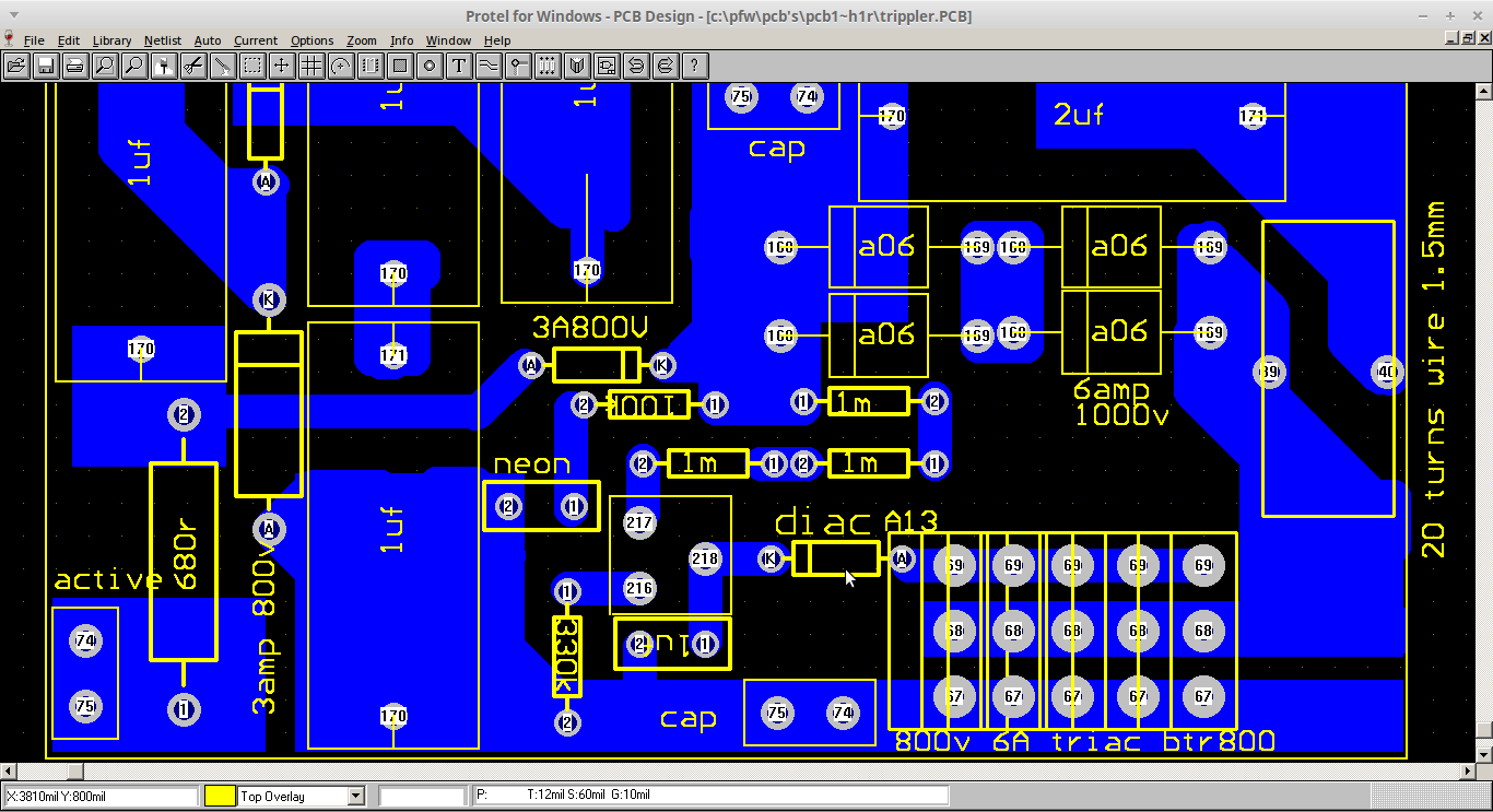
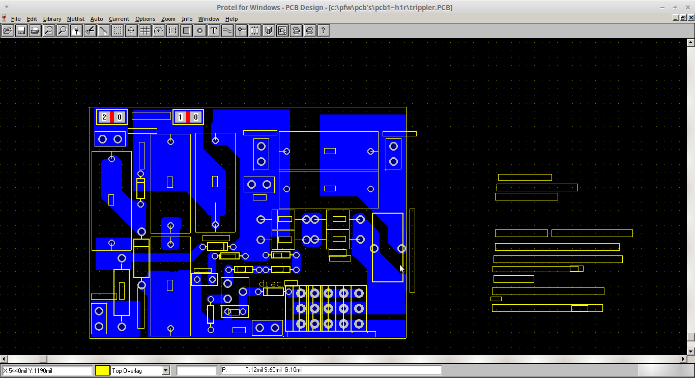
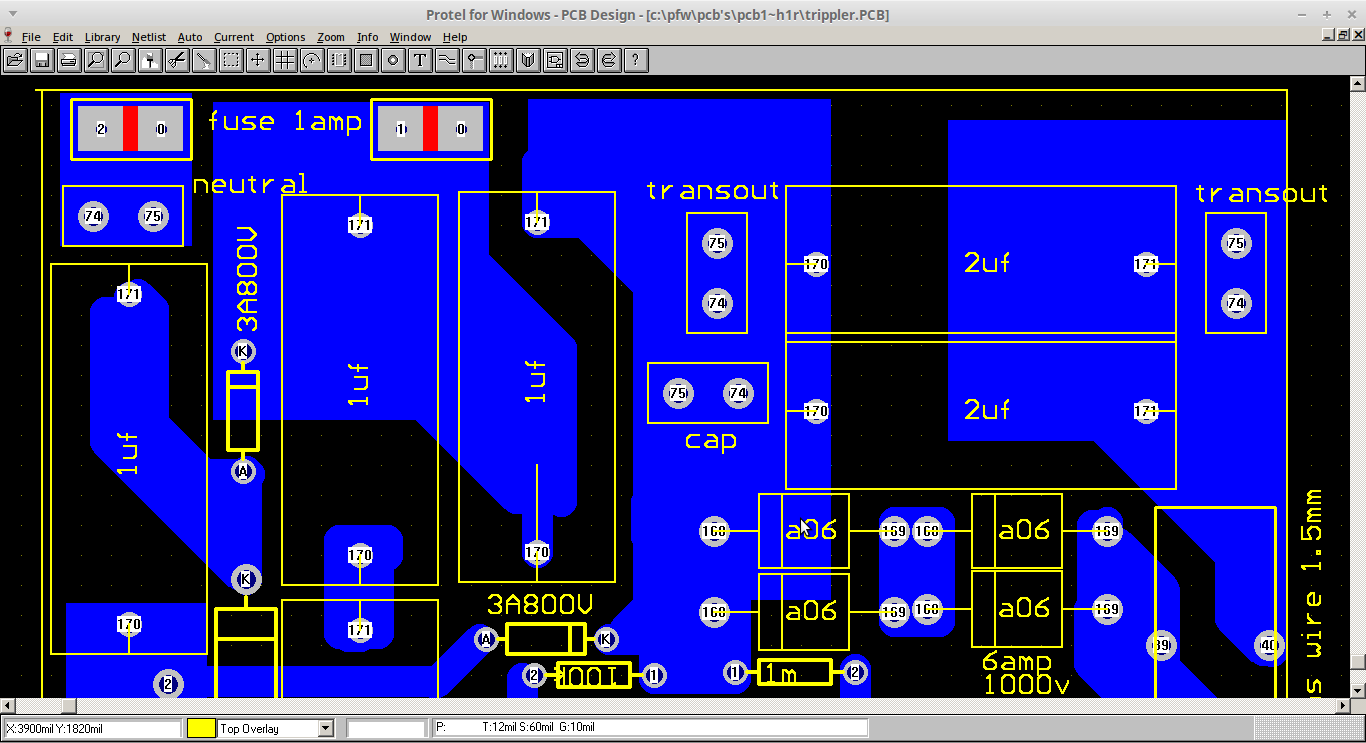
Here are the pics of the screen of the pcb program... where it gets designed from scratch on the run.. so no circuits unless you do one for everyone else.

To get the values up, the screen shot does not fit, so print them out and mosaic them if you have to.

Transformer is from a micro wave. Split open wiring discarded, and rewound as per instructions ... wind it as a HV transformer... ie separate each layer of wire to stop arcing internally.
First part of the screen
4527-0

second part of the screen
4529-1

pattern complete
4531-2

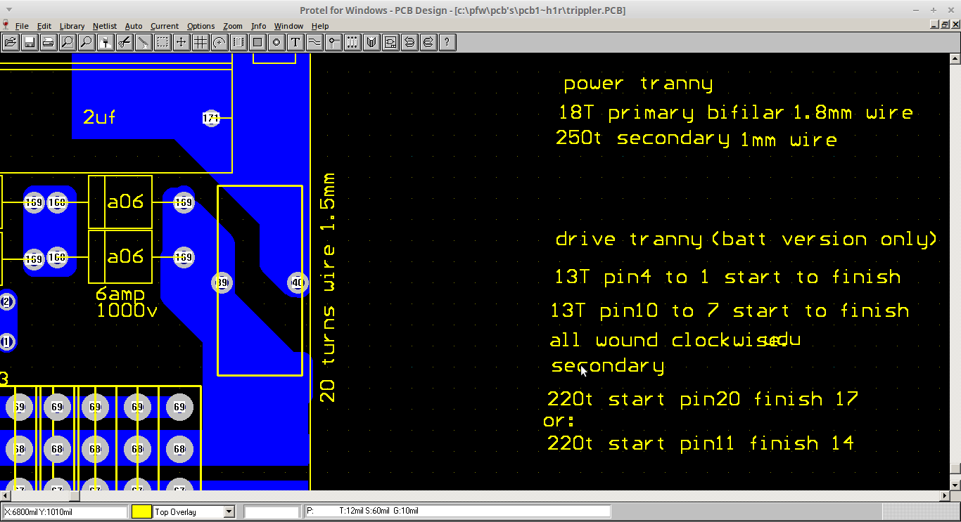
wiring of the power transformer. Ignore the battery step up instruction.... just the top instructions
4533-3

I may get some finished pics for you later today.


Notes: This is the newer version, and is a trippler. So it can develop 900 volts on the primary of the output transformer... beware!!
The trim pot next to the diac is about 100k.
The 1 and 2 uf caps on the board should be AC types. I find the 375vac ones to be fine.

The 1uf cap at the bottom center is 50v. It won't trigger without this cap.

The neon is anything you can find... just a signal for you, does nothing else.

Transformer terminals are marked.

The storage caps will need to be 900vdc or use 2 x 400vac 20uf or more in series instead. They use the terminals marked cap

On the left are the 240v inputs... marked as active and neutral.

Be very careful, this is a large size fencer, and good for 80km or more of fence... it is not a toy.

The bifilar primary is two in hand 1.8mm wire. The secondary is 1mm wire. It is mains connected, so double insulation of the primary from the secondary is mandatory, and of the primary and the core..

 This is a low impedance fencer, and will develop 250000 watts or more for millionths of a second.... don't be on the wrong end. The pulse won't kill as the duration is too small, but it will sit you down very powerfully...... multiple pulses (getting snared/caught in fence) will probably kill eventually... so DO NOT USE BARBED WIRE IN AN ELECTRIFIED FENCE it is illegal for this reason.

Keep the pulse rate to a second or MORE not less. You need time to get away from the fence if hit. The 680r can be increased for this.
The 100k pot changes the step off voltage, and as such affects the frequency of pulse.


The 900v on the primary will kill. It is both mains connected and 900v as well. Treat it carefully, even if using an isolation transformer for testing.

Unless your competent at building mains circuits, this is not for you unsupervised.

If your only half confident, get some supervision from a competent person. These circuits are  dangerous things, and need to be treated as such.

Always have a 500r 20w resistor across the output in place of the fence to keep extra high voltage from damaging your transformer. Unloaded these will run 10000v or more.

These fencers are dangerous.... yes, but not overly so... example is I am surrounded on this island by thousands of kilometers of electrified fences, so while the warnings are justified, they are not to be feared, but due care and caution is mandatory...... the darn things bite hard.

I have seen wallaby dead in fences around the place, and heard of cows dead in fences too. So prolonged exposure to pulses will kill huge beasts of 1000kg or more. Don't allow yourself to get in that position. Be very wary.

...................oztules

Flinders Island...... Australia

Offline oztules

  • Forum Advisors
  • Hero Member
  • ****
  • Posts: 1177
  • Karma: +105/-8
  • Village idiot
Re: Electric Fence Zapper
« Reply #224 on: September 26, 2015, 05:48:50 pm »
here are some pics to help

connections to external world

4536-0

close up of board with connections.

4537-1

more of the same

4538-2

Transformer

4539-3

...............oztules
Flinders Island...... Australia