Author Topic: An invitation to the electronic wizards in the forum  (Read 12810 times)

0 Members and 1 Guest are viewing this topic.

Offline David HK

  • Sr. Member
  • ****
  • Posts: 250
  • Karma: +21/-0
  • No Personal Text Set by User
An invitation to the electronic wizards in the forum
« on: May 22, 2012, 08:13:07 pm »
Who can help?

The story so far is that I have a Gardena model WT 1030 water sprinkler. The unit splits into two pieces which consists of the electronics and battery, and the solenoid and valve unit. The battery is 9 volts PP3 type.

Whilst making up a 9 volt DC circuit to supply power to the unit instead of the battery I think I accidentally supplied around 13.7 volts which has zapped the SMD 16 pin IC controller. I have checked the solenoid with a low volt circuit incorporating a 1K resistor and LED and that is in working order.

The operation of the solenoid is important and I will give a brief note here. It works on a Negative pulse to turn on and a Positive pulse to turn off. The Negative and Positive pulses cause the solenoid to attract or repel a small plunger valve to move about 1 to 2 mm to cause flooding around a rubber diaphragm. Thereafter water pressure along keeps the diaphragm opened or closed as the case may be. The duration of the pulses is not known except to observe on an analogue meter they seem to be about 1 second and the needle swings to about 9 volts or slightly less.

The cost of a brand new controller is HK$500 so I have set myself a challenge to build a new controller unit to work with the existing solenoid and valve unit for the same value or less.

Locally I can obtain an ANLY weekly programmable weekly timer for HK$360. Details of this unit can be found at:-

http://www.anly.com.cn/english/pdf/APT8(9)S(M)DA.pdf

The ANLY PDF is fairly comprehensive and readers should note that is can provide a pulse output which can be varied in width.

In the next block of electronics I have to find a way of using the ON and OFF pulses to cause the solenoid to change polarity. A flip flop of some sort comes to mind, but which type?

There is an interesting IC 4017 circuit which can be used as a flip flop on positive going pulses which can be found here:-

http://electroschematics.com/5504/toggle-switch/

After the flip flop section I have on order a MAXIM 4427 IC non-inverting type which can be used to change the polarity on the solenoid. A copy of the PDF can be found here:-

http://datasheets.maxim-ic.com/en/ds/MAX4426-MAX4428.pdf

A photograph of a MAXIM 4427 can also be found here:-

http://www.robotroom.com/HBridge.html

Scroll down the page to see a bread board photograph.

Other parameters:-

The timer and all other parts must suit DC 12 volt operation.
My knowledge if electronics is mediocre. I can build circuits from diagrams and design PCB’s from circuits, but I have never been schooled enough in the actual component layout of circuits.

I hope I have supplied readers with sufficient details, if you requite more I shall do my best to assist.

Regards,

David in HK


Offline rossw

  • Senior Moderator
  • Hero Member
  • *******
  • Posts: 879
  • Karma: +35/-0
  • Grumpy-old-Unix-Admin
Re: An invitation to the electronic wizards in the forum
« Reply #1 on: May 22, 2012, 10:13:34 pm »
Locally I can obtain an ANLY weekly programmable weekly timer for HK$360. Details of this unit can be found at:-

Thats still fairly expensive for what seems a fairly straightforward device.

Is your intended "fix" going to run from a 9V 216/PP3 battery, or something more substantial?
How many daily or weekly cycles are you anticipating?

Quote
In the next block of electronics I have to find a way of using the ON and OFF pulses to cause the solenoid to change polarity. A flip flop of some sort comes to mind, but which type?

David, I appreciate you trying to do this "the right way", but sometimes it only needs to be "good enough".
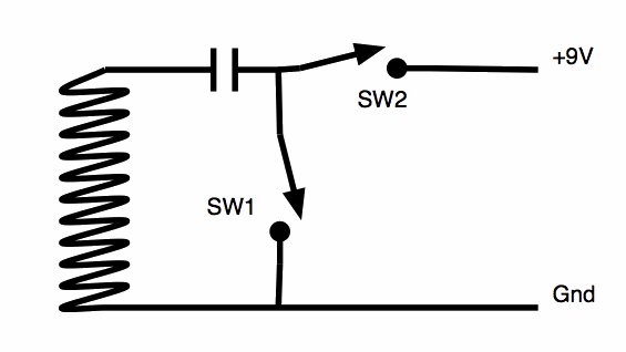
If you put a decent capacitor in series with the solenoid..... wait, let me draw it...
1184-0

If the capacitor is lets say, 470uF, when you close SW2, you will get a pulse of current through the coil with + at the top end.
Leaving the switch closed makes little difference to current - it will taper off as the cap charges, eventually ending with virtually nothing.

Release SW2, and close SW1 and the capacitor will now discharge through the coil - with the opposite polarity!

Replace the switches with transistors, and you can get your "open" and "close" polarity pulses without ANY expensive driver chips, H-bridges and mucking about...

Or you could use a single-pole double-throw relay to achieve the same thing.

Quote
The timer and all other parts must suit DC 12 volt operation.

I just purchased a timer to replace a failed mechanical one to run my pool pumps. Cost me $8.99 AUD (including delivery). It runs on 220V AC (although they also have a 12V version), has a nice digital display and 16 programmable events over a week. Each event has selectable on and off times and days, including selecting the day, every-day, week-days, weekends, mon-sat etc - so highly selectable. OK, it doesn't have selectable output pulse width - but if you use the capacitor idea, you don't need it to.

Just my thoughts....

Offline frackers

  • Full Member
  • ***
  • Posts: 239
  • Karma: +9/-0
  • If it moves - computerise it!
Re: An invitation to the electronic wizards in the forum
« Reply #2 on: May 22, 2012, 10:54:52 pm »
http://yahee.en.alibaba.com/product/318858932-210265811/7_Day_LCD_Electronic_Plug_in_Digital_Timer_Switch_24hr_YHA_PC092.html, a 9v universal wallwart, a relay and the cap as details by rossw should do the lot!!

Here in NZ these 7 day timers are about NZ$8 ( < HK$50).

BTW: These solenoids uses a magnet as the plunger hence being reversible and latching at each end of its travel :)


Robin Down Under (or are you Up Over!)

Offline rossw

  • Senior Moderator
  • Hero Member
  • *******
  • Posts: 879
  • Karma: +35/-0
  • Grumpy-old-Unix-Admin
Re: An invitation to the electronic wizards in the forum
« Reply #3 on: May 22, 2012, 11:04:05 pm »
, a 9v universal wallwart, a relay and the cap as details by rossw should do the lot!!

Here in NZ these 7 day timers are about NZ$8 ( < HK$50).

David specifically said it had to run on 12V, so the timer you cited isn't really suitable.

I was thinking something more like http://tinyurl.com/d7r8w9m - just over $10 AUD (under $80 HKD).
Runs on 12V, has a *changeover* relay for the output.

Ie, using one of these timers and a pre-existing power source, his *ONLY* other component would be the capacitor.

Offline David HK

  • Sr. Member
  • ****
  • Posts: 250
  • Karma: +21/-0
  • No Personal Text Set by User
Re: An invitation to the electronic wizards in the forum
« Reply #4 on: May 23, 2012, 07:39:42 pm »
Ross and all the other people who have read this article - thank you.

Ross, I note your comments about another timer in your second thread. Do you have access to a PDF or information sheet about it?

Yes. I want to stick to 12v DC because it suits my RE system.

As for watering times – right now I am water-on for three minutes at 7 am, and a repeat cycle 12 hours later at 7pm. In the autumn and early spring I often change this to three cycles at 8 hours each with a run time of 1 minute. It depends on what I need to water.

This thread needs to linger on for a while so that people like Ghurd can give it the once over.

Lets see if any other forum members have wiser thoughts.

Regards,

David in HK

Offline rossw

  • Senior Moderator
  • Hero Member
  • *******
  • Posts: 879
  • Karma: +35/-0
  • Grumpy-old-Unix-Admin
Re: An invitation to the electronic wizards in the forum
« Reply #5 on: May 23, 2012, 07:49:15 pm »
Ross, I note your comments about another timer in your second thread. Do you have access to a PDF or information sheet about it?

I found some docs here:
http://www.automaticsolutions.com.au/assets/manuals/index.php?dir=&file=7daytimer-quickstart.pdf

In my previous post, I posted a link to someone selling them for about $10
http://tinyurl.com/d7r8w9m

I have one sitting on my desk here that arrived this week - except that it runs on 240AC, it's otherwise identical, and should be fine for your job.


Quote
As for watering times – right now I am water-on for three minutes at 7 am, and a repeat cycle 12 hours later at 7pm. In the autumn and early spring I often change this to three cycles at 8 hours each with a run time of 1 minute. It depends on what I need to water.

The only potential problem with the timer I cite is that it has a MINIMUM operation time of 1 minute.
You have PLENTY of operations though - 16 or 17 program on+off times (cycles), if you do it "every day" then you only need 2 or 3 of them.

For $10 plus lets say $1 for a thousand microfarad capacitor, you'd be done....

Offline Wolvenar

  • Senior Moderator
  • Hero Member
  • *******
  • Posts: 1474
  • Karma: +40/-0
  • Mr. Murphys pawn
Re: An invitation to the electronic wizards in the forum
« Reply #6 on: May 23, 2012, 09:17:52 pm »
I like Ross's approach.
KISS principal many time fits the best.
I have similar setup for our garden, but I have never even considered putting it on the offgrid system until this thread, thanks for the idea and links Daivd/Ross
Trying to make power from alternative energy any which way I can.
Just to abuse what I make. (and run this site)

Offline David HK

  • Sr. Member
  • ****
  • Posts: 250
  • Karma: +21/-0
  • No Personal Text Set by User
Re: An invitation to the electronic wizards in the forum
« Reply #7 on: May 24, 2012, 08:30:09 pm »
Ross,

Could you confirm that the following drawing is a correct version of your earlier drawing above.

David in HK

Offline David HK

  • Sr. Member
  • ****
  • Posts: 250
  • Karma: +21/-0
  • No Personal Text Set by User
Re: An invitation to the electronic wizards in the forum
« Reply #8 on: May 24, 2012, 08:31:30 pm »
In the above drawing ignore the green line going to pin 9

David

Offline rossw

  • Senior Moderator
  • Hero Member
  • *******
  • Posts: 879
  • Karma: +35/-0
  • Grumpy-old-Unix-Admin
Re: An invitation to the electronic wizards in the forum
« Reply #9 on: May 24, 2012, 08:35:56 pm »
Ross,

Could you confirm that the following drawing is a correct version of your earlier drawing above.

That looks fine.
Of course, if you use the timer that I linked to, you don't need the (extra) relay as it already has a changeover (SPDT) output.

If you do choose to use a seperate relay as per your diagram, I'd *STRONGLY* advise a freewheeling diode across its coil to reduce the potential of nasty spikes back into your system.

Also, leave plenty of room around the capacitor. I've no idea what the current requirement of your solenoid is, and suggested a nominal capacitor that I "think" would likely do. You MAY have to use a larger cap. Conversely, you might get away with a smaller one. Take a 12V battery outside, 3 clip-leads and a selection of electrolytic caps from your junkbox. Find the smallest cap that will reliably turn it on and off, then use twice that in your final circuit :)

Offline David HK

  • Sr. Member
  • ****
  • Posts: 250
  • Karma: +21/-0
  • No Personal Text Set by User
Re: An invitation to the electronic wizards in the forum
« Reply #10 on: May 24, 2012, 08:37:12 pm »
Another piece of guidance needed.

The original Gardena solenoid coil probably operated at 9 volts maximum.

If I put 12 volts through it what will happen?

David in HK

Offline rossw

  • Senior Moderator
  • Hero Member
  • *******
  • Posts: 879
  • Karma: +35/-0
  • Grumpy-old-Unix-Admin
Re: An invitation to the electronic wizards in the forum
« Reply #11 on: May 24, 2012, 08:42:07 pm »
The original Gardena solenoid coil probably operated at 9 volts maximum.

If I put 12 volts through it what will happen?

It will draw more current and make a stronger magnetic field.
Since you will have a capacitor in series with it, the duty-cycle will be VERY low.
If you were going to be a purist, you'd measure the DC resistance of the coil, work out what current it would have taken at 9V, then work out the series resistor required to limit the current to that when running on 12V, and put that in series with the cap.

Eg, lets say you measure the coil and it's 90 ohms.
It would take 100mA from a 9V source.

In order for it to draw only 100mA from your 12V supply, the total resistance needs to be 120 ohms, so you'd use a 30 ohm resistor in series. (90+30=120). 30 ohm isn't a common value, so use a 27 ohm resistor.

My friend the bot tells me:

<RossW> !ohmslaw 27r 100ma
<RossBot> 2.700 volts at 100.000 milliamps through 27.000 ohms for 270.000 milliwatts

You would only need a 1/4 watt resistor.

Reality is: it's such a short pulse, its unlikely to be a problem even without the resistor.

Offline David HK

  • Sr. Member
  • ****
  • Posts: 250
  • Karma: +21/-0
  • No Personal Text Set by User
Re: An invitation to the electronic wizards in the forum
« Reply #12 on: May 24, 2012, 08:47:58 pm »
Ross,

Thank you for the very useful advice and your time.

I have updated the drawing and included a diode across the relay coil - I hope its the correct alignment.

Dave

Offline rossw

  • Senior Moderator
  • Hero Member
  • *******
  • Posts: 879
  • Karma: +35/-0
  • Grumpy-old-Unix-Admin
Re: An invitation to the electronic wizards in the forum
« Reply #13 on: May 24, 2012, 08:50:58 pm »
I have updated the drawing and included a diode across the relay coil - I hope its the correct alignment.

Yes, that's fine. But if you're going to make a board, at least add a the option of a resistor in series with the cap.
Put it down as two pads the right spacing apart, run a track between the two so the "default" condition is that it's shorted, but if you choose to put in a resistor (or two back-to-back zeners) you can solder them in and cut the track. No need to re-make the board :)

Offline David HK

  • Sr. Member
  • ****
  • Posts: 250
  • Karma: +21/-0
  • No Personal Text Set by User
Re: An invitation to the electronic wizards in the forum
« Reply #14 on: May 24, 2012, 09:03:11 pm »
Thanks Ross,

Another refined drawing attached.  I had not planned to make a board at the moment, I'm just concentrating on getting the circuit layout correct. Not doing too badly today with a slight hangover - may go for a hair of the dog shortly.

Dave