Author Topic: Buck converter for small wind turbine project  (Read 77956 times)

0 Members and 1 Guest are viewing this topic.

Offline Burnit0017

  • Full Member
  • ***
  • Posts: 191
  • Karma: +0/-0
  • No Personal Text Set by User
Buck converter for small wind turbine project
« on: January 08, 2012, 07:16:57 am »
Greetings, I am new to the forum. I recently constructed and tested a working PMA and VAWT. At 40 MPH it will produce 9 amps DC using a 12 volt deep cell for a test load.


I started a project for a very basic buck converter to determine if it will produce a higher output from my PMA at a lower wind speed.

As I understand the circuit charges the output inductor when the MOSFET is on.
When the MOSFET is off, the turbine will be allowed to maintain a higher RPM and the energy stored in the inductor will discharge current into the battery.

The output voltage will always be fixed to the battery voltage.
The input voltage will change as the turbine RPM changes.
The input voltage will be high with low current and the output voltage will be low with higher current because the energy stored in the large output inductor will discharge into the battery as the MOSFET turns on and off.

I have all the parts to fabricate a very basic low amp output buck converter.
I am trying to design the basic test circuit so a micro controller can be added if required.
This is a first attempt at designing a power circuit. I have a basic understanding of all the concepts involved and comments are welcome.


Mod Edit: Removed the You-Tube Clip as it promotes that Snake Oil guy

Offline Burnit0017

  • Full Member
  • ***
  • Posts: 191
  • Karma: +0/-0
  • No Personal Text Set by User
Re: Buck converter for small wind turbine project
« Reply #1 on: January 08, 2012, 07:53:50 am »
Hi, I started fabrication of the output part of the circuit. There will be three separate circuit boards:
1. diode and output inductor
2. MOSFET and input capacitor
3. timing circuit

I have used the timing circuit on other project so I know it will work.
I am using this article as a guide to determine component valves.
 Power Electronics Technology_ June 2006 “Buck-Converter Design Demystified”

http://my.ece.ucsb.edu/Bobsclass/194/References/NonIsolated/Buck/Buck%20Converter%20Design%20Demystified%20606PET25.pdf


I have to determine what switching frequency will work best for this application?


Comments welcome.   

Offline Wolvenar

  • Senior Moderator
  • Hero Member
  • *******
  • Posts: 1474
  • Karma: +40/-0
  • Mr. Murphys pawn
Re: Buck converter for small wind turbine project
« Reply #2 on: January 08, 2012, 09:04:40 am »
Nice post, I think I will be watching that guys progress and yours.
This now gives me ideas for a project.
Trying to make power from alternative energy any which way I can.
Just to abuse what I make. (and run this site)

Offline Burnit0017

  • Full Member
  • ***
  • Posts: 191
  • Karma: +0/-0
  • No Personal Text Set by User
Re: Buck converter for small wind turbine project
« Reply #3 on: January 09, 2012, 07:53:13 am »
 http://www.aliexpress.com/product-fm/488055373-150W-500W-wind-controller-12v-24v-switched-auto-wholesalers.html

Hi, commercially availably MPPT.

-->Mod EDIT.
Generally we will wish for a certain number of posts before allowing links to outside sites.
This is to discourage, and control spammers and search engine loaders.

However there has not been a consensus among the mods and admins of what this number should be.
As such we have not posted that in any rules as of yet (early days).

All that aside, this IS the kind of link that IS RELEVANT, and fitting to the topic.
This link also does not appear its meant for any alternative agenda such as boosting a site ranking
A posting like this as per moderators discretion MAY  be over looked for these reasons even if that
future posting number had not been reached.

Thank you for the good example Burnit0017

<--

Offline Burnit0017

  • Full Member
  • ***
  • Posts: 191
  • Karma: +0/-0
  • No Personal Text Set by User
Re: Buck converter for small wind turbine project
« Reply #4 on: January 09, 2012, 02:13:35 pm »
Hi, I am making progress. I purchased more binding posts so I can more easily change the cap and inductor with different values.  I am working on the gate oscillator. The biggest challenge is finding away to connect the boards that will able to carry the increased current. The first test circuit will have a five amp maximum limit mainly because the only diodes I could find have a 3 amp rating. I am running two in parallel.  What I find curious  is the inductor I fabricated from the equation provided in the article would not fit in their case.  I have no association with commercial item. 

Offline Burnit0017

  • Full Member
  • ***
  • Posts: 191
  • Karma: +0/-0
  • No Personal Text Set by User
Re: Buck converter for small wind turbine project
« Reply #5 on: January 11, 2012, 09:05:07 am »
Hi, project update.
Waiting for ordered parts.
I found a link that shows sensor to measure current if micro control is required.

http://scienceshareware.com/how-to-measure-AC-DC-current-with-a-hall-effect-clamp-.htm


I do not know if the switch frequency has to be adjustable for the circuit to function at different wind speeds.


Offline oztules

  • Forum Advisors
  • Hero Member
  • ****
  • Posts: 1177
  • Karma: +105/-8
  • Village idiot
Re: Buck converter for small wind turbine project
« Reply #6 on: January 13, 2012, 03:16:37 pm »
The switch frequency has no bearing on the function.... just the design difficulty.

Use a set frequency, and change your pulse width (duty cycle) to achieve whatever control parameters you are going to use via your controller.

For a first time go, I have these simple rules I have garnered from blowing up lots of fets.

Keep the frequency low (20khz).
Make a current limiting circuit part of your design
Drive the fets with a low impedance driver (transformer or dedicated driver or high current driver )
Separate the grounds so interference from the power stage does not leak into the signal stage
Dont saturate the core........ and....
Do it in the basement so no-one can hear the Fets scream before they toddle off into the afterlife.

A lot has been said to NOT breadboard these pwm things. It is mostly true, and a lot of design work is done to get the layout perfect.... to protect against stray leakage etc.

At lower frequencies, this is also true, but you can still do a whole lot of interesting things at the birdsnest stage, and get results to move on with. It is surprising what will actually work in a mess..... until you turn the current up that little bit more..... then it can be problematic.

Try hard to turn the fets fully on fast and fully off fast...... with a very square wave. This is where the dreaded heat can be bought down to an acceptable level from a otherwise cooking fet.


I would experiment with analogue devices first until you get the feel of control and how things work.... then you can confuse the issues further with programming, as by then you will know how varying the parameters actually change the workings of the switcher.

My experiences with PWM tells me an oscilloscope is virtually mandatory. Without it, your at a loss to fault find and correct poor performance when it is attached to wave form, and switching times, leakage, damping, peak switching voltages, spikes etc etc. 

I found PWM switching is a minefield of things waiting to destroy your fets, but when you beat the problems one by one it is rewarding.


Just my take on it anyhow. Hope it helps


................oztules


Flinders Island...... Australia

Offline Burnit0017

  • Full Member
  • ***
  • Posts: 191
  • Karma: +0/-0
  • No Personal Text Set by User
Re: Buck converter for small wind turbine project
« Reply #7 on: January 13, 2012, 04:34:45 pm »
  Hi, I received a recommendation to add a voltage comparator that would turn off the MOSFET when the input voltage is lower than the battery voltage. This will be the first circuit to determine what else will needed for buck converter. I should be able measure input current and compare it the output current. Because the controller circuit will be on a bread board it will be easy to make improvements after I have a working buck converter.

Thank you for the information. I ordered the O scope. If I can get this first test running than I can make improvements.

Offline Burnit0017

  • Full Member
  • ***
  • Posts: 191
  • Karma: +0/-0
  • No Personal Text Set by User
Re: Buck converter for small wind turbine project
« Reply #8 on: January 19, 2012, 09:13:12 pm »
Hi, the new used oscilloscope arrived. It displays the calibration wave form on each channel. What connections are needed to view the AC output of the PMA?   

Offline rossw

  • Senior Moderator
  • Hero Member
  • *******
  • Posts: 879
  • Karma: +35/-0
  • Grumpy-old-Unix-Admin
Re: Buck converter for small wind turbine project
« Reply #9 on: January 19, 2012, 09:27:20 pm »
Hi, the new used oscilloscope arrived. It displays the calibration wave form on each channel. What connections are needed to view the AC output of the PMA?   

Ahh, posting on both.... thats fine, I'd far rather respond here anyway. We don't have so many argumentative ignoramuses :)

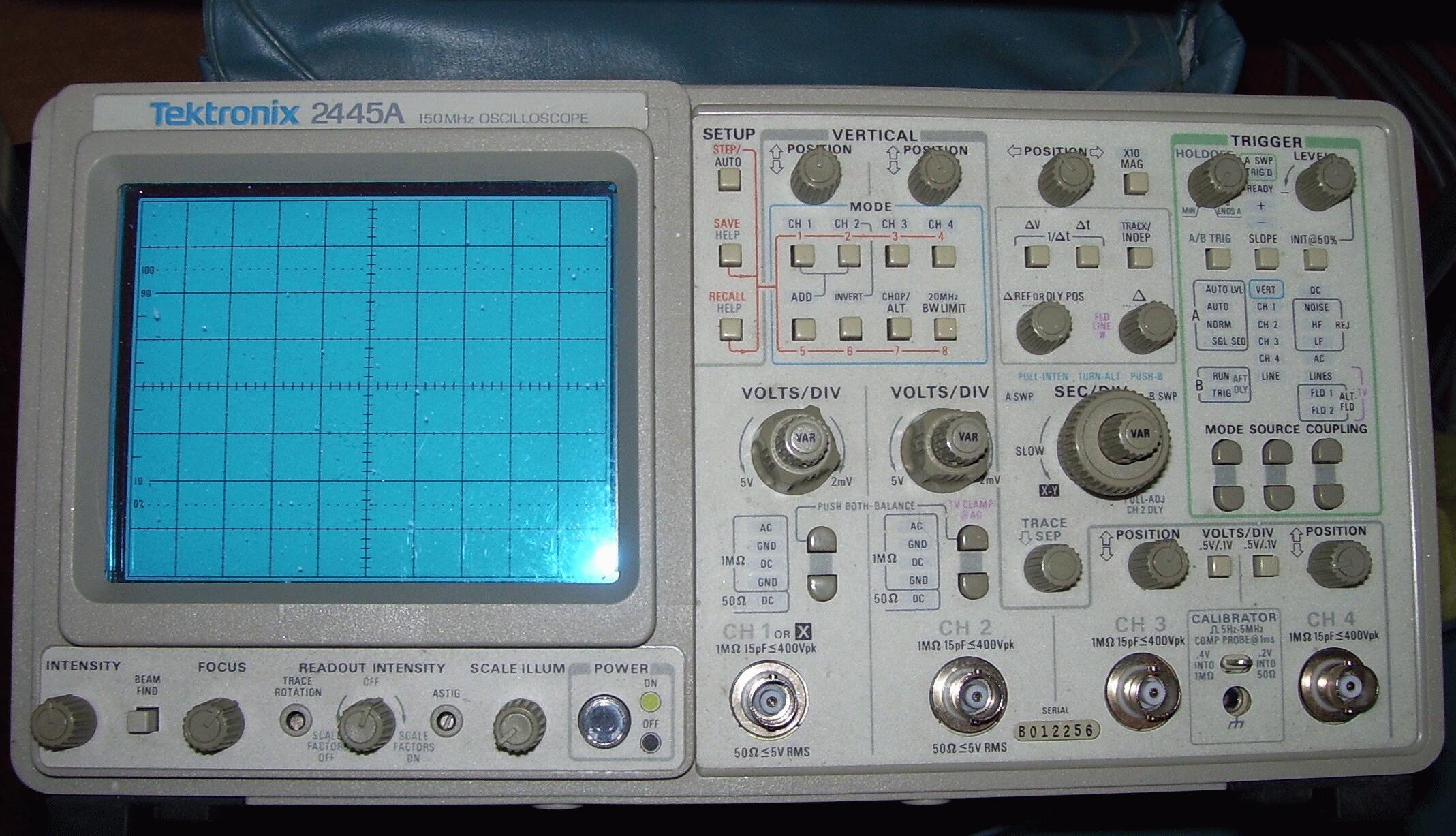
I've got a similar scope - couple of models up I think, the Tek 2445.


If you connect ONLY ONE CHANNEL with the input of that channel set to DC (not AC, reason later), and clip your input lead across any one coil (that's any two phase wires if they're in delta, or any phase and the star point in star/wye), you should see one phase (one of the three).

DO NOT CONNECT MORE THAN ONE CHANNEL AT THIS TIME, because you will find that all channels "ground" is the same. Putting more than one channel on, will very likely let out magic smoke. ALSO, CHECK FIRST that your 'scope ground doesn't have any potential to your generator output - star point or whichever phase you wish to use for the earth. If it does, you will need an isolating transformer for the scope.

In the absence of a suitable transformer, you MAY get away with using a suitable voltage, AC-rated capacitor in series with the ground lead of your scopes input. Around 2.2uF 630V would be a good place to start.

Edit: I forgot. The reason for DC not AC is that your input signal could be fairly low frequency, and the AC coupled input on the scope will affect how it displays your signal. It may not display it at all, whereas the DC coupling will show you exactly what's going on, including any DC offset.

Offline Burnit0017

  • Full Member
  • ***
  • Posts: 191
  • Karma: +0/-0
  • No Personal Text Set by User
Re: Buck converter for small wind turbine project
« Reply #10 on: January 20, 2012, 10:01:37 am »
Hi, thank you for the help. Spinning the PMA by hand I am to confirm that the PMA does produce a sine wave output.
   

Offline Burnit0017

  • Full Member
  • ***
  • Posts: 191
  • Karma: +0/-0
  • No Personal Text Set by User
Re: Buck converter for small wind turbine project
« Reply #11 on: January 21, 2012, 04:33:12 pm »
Hi,  I spent the last few days trying to get the nand gate oscillator to oscillate and show the output wave form on the O-scope. Step one complete, next is the voltage multiplier. I will post updates when available. 

Offline Burnit0017

  • Full Member
  • ***
  • Posts: 191
  • Karma: +0/-0
  • No Personal Text Set by User
Re: Buck converter for small wind turbine project
« Reply #12 on: January 21, 2012, 06:24:42 pm »
Hi, 10 volts in, 20 volts out. Voltage multiplier is working. It is time to add a mosfet and the control circuit for input A.

Offline oztules

  • Forum Advisors
  • Hero Member
  • ****
  • Posts: 1177
  • Karma: +105/-8
  • Village idiot
Re: Buck converter for small wind turbine project
« Reply #13 on: January 21, 2012, 07:03:27 pm »
Nice waveform..... look at it long and hard...... coz thats the shape you want to see on the gate/s when the current starts to get going. Not always easy.


..............oztules
Flinders Island...... Australia

Offline Burnit0017

  • Full Member
  • ***
  • Posts: 191
  • Karma: +0/-0
  • No Personal Text Set by User
Re: Buck converter for small wind turbine project
« Reply #14 on: January 22, 2012, 07:53:26 am »
Hi, The RC timing constant at the voltage multiplier output is not allowing a pulsed output. The output of the voltage multiplier has 1.5 volt ripple riding at 20 volts and is not discharging to zero, so the MOSFET will never turn off when point A is enabled. I am searching for alternatives. Ordering a gate driver is the obvious solution. Comments welcome.