Author Topic: Mig Welder Transformers  (Read 4486 times)

0 Members and 1 Guest are viewing this topic.

Offline solarnewbee

  • Full Member
  • ***
  • Posts: 231
  • Karma: +1/-0
    • Cayenne Dashboard
Mig Welder Transformers
« on: May 20, 2016, 07:23:08 pm »
Anyone know if this thing can be made into an inverter? It's from a 90 flux core mig welder I wasn't using anymore and curious if I tie in with my spare PJ boards what the results might be or if I'm pissing up a rope.

Could be it's worth lunch money from the scrap yard

Regards All
SN

Any day above ground is a day for potential mishaps

Offline oztules

  • Forum Advisors
  • Hero Member
  • ****
  • Posts: 1177
  • Karma: +105/-8
  • Village idiot
Re: Mig Welder Transformers
« Reply #1 on: May 20, 2016, 11:19:00 pm »
Yes it would work for a kw or two.... needs some rework I expect.... will be twice as lossy as a torroid... but if thats not a problem then yes,  pull it apart, and rewind the primary wire ( thick one ) to the voltage you want (27v for 48v using the 8010, or 30v for the pj cards).....

Trouble may be in taking it apart.


..............oztules
Flinders Island...... Australia

Offline Pete

  • Sr. Member
  • ****
  • Posts: 385
  • Karma: +19/-1
  • Mount Barrow Tasmania
Re: Mig Welder Transformers
« Reply #2 on: May 21, 2016, 01:38:34 am »
Oztules, i don't see why they would have to take the transformer apart, it looks like there is enough room to just unwind the primary in situ.
Then rewinding a new primary would be pretty simple really. Like you say unstacking the core would be pretty painful.
I can't say anything about the turns ratio, you seem to have that covered, although i find your post a little cryptic. What is an 8010?
Primary turns will also depend on the battery voltage  that solarnewbee is using  surely.

Offline oztules

  • Forum Advisors
  • Hero Member
  • ****
  • Posts: 1177
  • Karma: +105/-8
  • Village idiot
Re: Mig Welder Transformers
« Reply #3 on: May 21, 2016, 03:38:39 am »
Hi Pete, and welcome to the board... fellow Tasmanian.

Firstly, the 8010 is actually referring to an eg8010 chip which is the heart of a  high power  pure sine wave inverter control card  we have developed recently, so is very likely familiar to Solarnewbee.

So if your gonna use a tranny to make  a pure sine wave unit, this is a very useful option... see here:

http://www.anotherpower.com/board/index.php/topic,1116.0.html

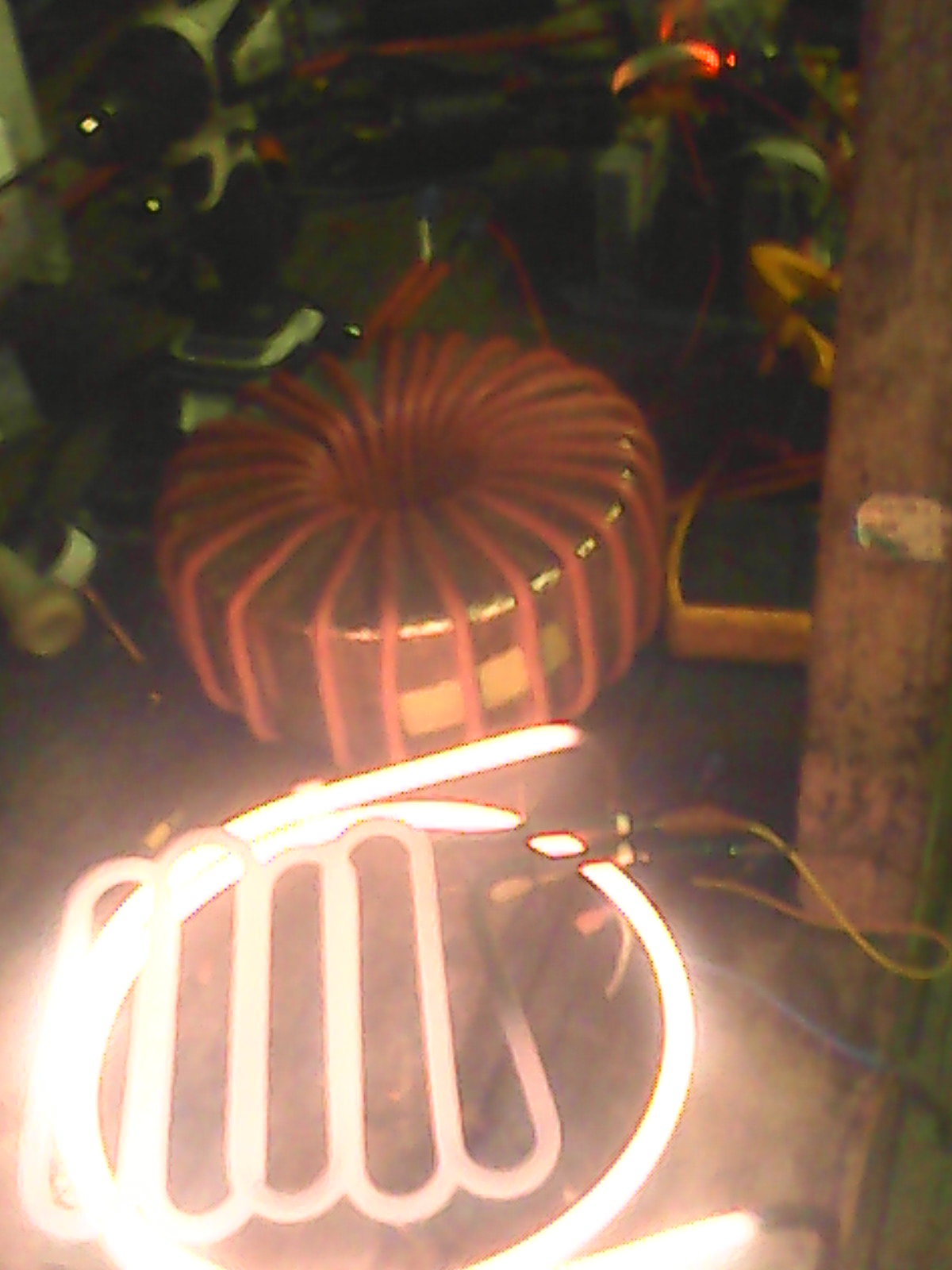
This is for the first testing of the egs002,which later we made the 8010 directly..... here it is (002 variety, no pics of the 8010 doing this) at 4000w using a torroid transformer with under sized primary ... 16mmsq wire
5674-0

The transformer we are talking about here has very poor use of the winding window, which is crucial for good duty cycle operation, at higher powers.... It was designed for low duty cycles, so it did not fry.

For a 1kw - 2kw pure sine we would need to take that core apart, as we need to get 12-16mmsq of copper in there, as a minimum... this will entail winding thick wires three in hand or more....and.. this requires a clear winding environment....

If you tried to do this as it is, you would have both a total mess, and more importantly, the enamel would have scraped on the sides of the core, and damage would occur... thick wire is not easy to handle ( 1.8mm and over )

Secondly the length of pull through would make this very unlikely even for single smaller wire....... the primary would probably need the same treatment.


The real problem is that I see no bolts holding the plates together.... pulling apart and redoing the plates is easy  in most cases, bigger is even easier, but...
 They may have welded the plates together like in microwave ones.... and this presents problems with eddy currents, which would kill this off for inverter purposes... yes I have rewound many and bigger and smaller... but large eddy currents will use too much power on idle, which will be twice the torroids before we use poor steel or have plates uninsulated .

Worse, they may have punched them together, and thats a real problem with reassembly... I suspect this is the case here.

So if he is to use this transformer as a useful inverter unit, we need full winding windows to keep the power handling up and the magnetising currents down.
Or the idle currents will make the inverter very hungry for power. The original PJ units consumed over 5kwh/day just to run no loads.... this is a problem we don't have anymore.

This article here http://www.anotherpower.com/board/index.php/topic,1044.0.html will give him enough information on how to size the windings as well as other tips so measuring the turns/volt will tell the story of turns, and current will go up or down according to voltage.... wire size..

The 8010 board takes any voltage, so does not matter, as does the 002.


.................oztules
Flinders Island...... Australia

Offline Pete

  • Sr. Member
  • ****
  • Posts: 385
  • Karma: +19/-1
  • Mount Barrow Tasmania
Re: Mig Welder Transformers
« Reply #4 on: May 21, 2016, 04:39:09 am »
Thanks for the explanation Oz. I have seen quite a few of those cheaply made low duty cycle transformers with welds to hold them together. Mongrels to get apart like you say, basically it is out with the grinder. I guess that they are not designed for efficiency are they, just cheap and nasty welders.
Thanks for the reference to the 8010 chip, I will have a read. I have a minimalist 12 volt solar setup, being an ex sparky I am pretty good at keeping power consumption down. We have a Powerstar W7 that I use as a heavy load inverter, but measured the standby current when I first got it and freaked out. I could not believe that they would build such an inefficient design. Read your article on fixing the standby by current.
I was wondering if with the new inductor setup you have and also with a transformer change in the W7 if that is all the mods that are necessary. It seems that the capacitor you changed on your W7 has either been altered on the new Power Jack boards or it is no longer necessary to change it.
Anyway thanks for the information, I may change my W7 over to torroid one day, that is when I find a reasonably priced tranny.
Oh I have had some experience with winding things, I used to be a motor rewinder, luckily we did not have to do too many transformer rewinds. Stacking EI cores is pretty ordinary.
Cheerio
Pete

Offline solarnewbee

  • Full Member
  • ***
  • Posts: 231
  • Karma: +1/-0
    • Cayenne Dashboard
Re: Mig Welder Transformers
« Reply #5 on: May 21, 2016, 04:06:44 pm »
Hey Oz and Pete! Good Day!

interesting read indeed. the feet brackets used to bolt it to the welder casing are slipped on then welded in place and then they used probably a 20 ton press to punch thru all laminations.

so,,,Lunch Money!!!! or a really heavy paper weight. only paid $80 for the whole welder and the control parts may come in handy. the only welding I do is if one of my customers has a small job i can knock out with a flux core(no gas) mig welder.

Oz your right I have been following your 8010 work and winding coils. something I would like to attempt someday when I get educated better and get up the nerve to experiment. when I finally retire to the philippines your gonna have to invite me to the island for a view. haha.

i've got about 200 irfb4110 fets so i might be playing around with some sort of design your playing with. I am starting to get the jist of adding and subtracting turns for voltage changes and how another board talked about raising the voltage up more towards 250v which out in the countryside here in south carolina the electric coop pumps 250-260 volts into homes for some reason. had a customer who kept losing microwaves and the line-man reach inside the pole transformer and turn a rotary switch then left a recording graph plotter to record line voltage.

I could make one hell of a microwave, hot pockets done in ten seconds.

I'm convinced now that these type transformers are just not suitable for our purposes. I have a spare PJ 8000 I might rewind and drop in my PJ if you hold my hand ;0 .

I order the pj 8000 main and control and they came assembled and ripped me on fedex charges. the toroid coil says O/P:0--16vac, whats the meaning? is that the lf voltage signal in? the metal band around it, does it have a purpose or just for protection. can that be whats humming in some PJ's?

Have a Great rest of your weekend guys  pics to follow


SN
SN

Any day above ground is a day for potential mishaps

Offline oztules

  • Forum Advisors
  • Hero Member
  • ****
  • Posts: 1177
  • Karma: +105/-8
  • Village idiot
Re: Mig Welder Transformers
« Reply #6 on: May 21, 2016, 05:46:12 pm »
Big older fashion welder transformers are probably quite good. I used a 1.5kw  transformer from a big charger from Hydro Tas, and rewound it, it works at about 1/2 the efficiency of the torroids, qhich is about as good as it gets I guess.

I have ground out and used microwave ones, making them 3-4 times as big for other projects, but need to insulate the plates and NOT reweld them. They work ok too.

That one you showed can work too, but a lot of work in disassembly of the plates.... then straighten them out to get rid of the punch marks.... and very much a labor of love, but can be made to work effectively.... the 16v is the nominal input voltage, and the shield is for noise abatement I think, as it is earthed from memory.

Pete, there are inspires, and cehe and aerosharp inverters from time to time on the net, freight is the problem to tassie, but a place in Brunswick sells them for $70, but none on there at the moment... I have 16 coming..... :)

The W&7is a good unit, but needs the inductor and another transformer.... you could try just inductors of different sizes, I tried only one and went to torroids.... maybe if I tried more things I would have found how to get the power back to decent, but mine was 5kwh/day (48v).... got it down to less the .5kwh/day.

The magnetic efficiency of the torroid is hard to pass up, as it makes the sag very small comparatively

...................oztules
.
Flinders Island...... Australia

Offline Pete

  • Sr. Member
  • ****
  • Posts: 385
  • Karma: +19/-1
  • Mount Barrow Tasmania
Re: Mig Welder Transformers
« Reply #7 on: May 21, 2016, 07:20:11 pm »
Hi Oz I tried an inductor on the W7 , I wound 3.5 turns on to a 65mm former, connected it to the positive terminal but it made no difference at all.
I may experiment later with more turns. Mine is a 3000watt, 12 volt unit. I don't use it to run anything like 3kw though.
I will keep an eye out for the aero sharp units, otherwise i may try an old welder transformer that i have. Thanks for the tips. Pete

Offline oztules

  • Forum Advisors
  • Hero Member
  • ****
  • Posts: 1177
  • Karma: +105/-8
  • Village idiot
Re: Mig Welder Transformers
« Reply #8 on: May 21, 2016, 09:23:56 pm »
" I wound 3.5 turns on to a 65mm former"
Was that a ferrite ecore or a steel former?

For these frequencies, you need ferrite, and to get the micro henries you need, you want a full magnetic circuit... so torroid or ecore... you need over 14uh of inductance as a start....   a steel bar or laminate will not cut it, nor will a ferrite bar.... needs a lot more turns without full magnetic circuit on a ferrite bar.

My W7 was a 6000w/18000w 48v unit.... good unit it was too... still runs, but new control card as a spider killed the original... story here... may help you.
http://www.anotherpower.com/board/index.php/topic,780.0.html


.................oztules
Flinders Island...... Australia

Offline Pete

  • Sr. Member
  • ****
  • Posts: 385
  • Karma: +19/-1
  • Mount Barrow Tasmania
Re: Mig Welder Transformers
« Reply #9 on: May 21, 2016, 11:59:47 pm »
Hi Oz I wound it on a ferrite E shape core.  The current with 4 turns of 25mm wire went down from 13.5 amps with no load to 7.8 amps. Still not as good as you got with the torroid but quite a saving. There isn't room inside the inverter for it so I will bring out a couple of leads to connect the inductor to.
I am guessing that if I added a couple of turns of wire to the primary of the transformer it would do the same job, but it is easier to just use the ferrite.
I may be wrong but it looks like the transformer core is saturated, thereby reducing the reactance of the windings. Adding the inductor increased the reactance and reduced the current.
That is my take anyway
Pete

Offline oztules

  • Forum Advisors
  • Hero Member
  • ****
  • Posts: 1177
  • Karma: +105/-8
  • Village idiot
Re: Mig Welder Transformers
« Reply #10 on: May 22, 2016, 01:36:29 am »
"I am guessing that if I added a couple of turns of wire to the primary of the transformer it would do the same job, but it is easier to just use the ferrite."
If you wind more on the both the primary and secondary, you will do a bit better, but I expect your window is full anyway. This would lower the magnetising current, and if we are near saturation, it would be non-linear, so a grater change than linear could happen....

However, I fully expect we not at  saturation, as we need a fair bit of head room to get a dynamic range out of the tranny at different loads, so they would not have done that.

The ferrite stops a lot of HF hash that may be involved in all kinds of evil things, but I think it is the time constant that changes in the nano seconds of fet conduction in the channel... ie there is fractionally more time for the channel to open due to the added inductance... nano seconds count.  Also some of the hf is filtered out, and eddy currents may be a bit lower... I don't have a definitive answer, but the uH is too small to be a real filter, but it works so well????

Saturation can only be caused by a change in voltage or frequency from the non-saturated state. Short circuit will not saturate the core. ( check equations).
In this case, the higher frequency should bring us further from saturation... so no idea really.

At least we halved your losses... this is big deal in itself.... well done.

.................oztules
Flinders Island...... Australia

Offline Pete

  • Sr. Member
  • ****
  • Posts: 385
  • Karma: +19/-1
  • Mount Barrow Tasmania
Re: Mig Welder Transformers
« Reply #11 on: May 22, 2016, 02:01:34 am »
Hi Oz thanks again for the help. I am only going on experience, not too big on the deep theory. I had a machine a few months back that a friend was trying to repair. It had a small induction motor only about 1kw on it that he brought to me to check. I had a look and it seemed fine, just needed a new bearing. He had to replace the Variable Frequency Drive for it and when he did it kept shutting down the drive. I had another look at the motor for him and realised that it was Delta connected. Now not many very small motors are Delta so I looked deeper. On the stator windings was a label that said 230/380 volt. The penny dropped then that the motor should have been Star connected for our 3 phase system. The motor in Delta was drawing somewhere around 20 amps and in Star only around 2 amps. So once it was properly connected it worked great. My guess was that with too many volts the core was saturating, that meant that the only thing limiting the current was the resistance of the windings. Taking resistance measurements backed that up. The end story was , we had no idea how the machine had been working at all except that if the VFD was set low enough the motor would have been fine, once the voltage came up then all hell broke loose.
These sorts of repairs are sent to try us aren't they.
Like you say the W7 is much better than it was but still throwing away nearly 100 watts is not ideal. Luckily it is only used to power tools in the shed.
You sound like you are a chronic tinkerer. Hope you are having fun.

Offline oztules

  • Forum Advisors
  • Hero Member
  • ****
  • Posts: 1177
  • Karma: +105/-8
  • Village idiot
Re: Mig Welder Transformers
« Reply #12 on: May 22, 2016, 03:31:58 am »
Hmmmm. A 230/380v motor will run in delta for 230v and star for 395v or thereabouts ( root3 x 230v).

Being a small motor I would have thought it was using a 240v single phase to 3 phase converter ( VFD)... that being the case, we would expect it to be wired in delta for 240v and star for 415v.

If you were using a 240v VFD, then I can only assume a stator fault is present, and changing to star alleviated the low impedance path, by hiding it in the star arms... in delta it would be directly across the VFD outputs..... ie the motor may be technically faulty, but you got around that. I expect it has much less power now, but it is not in a high torque application.... just my take.

Was it a 240 or 415v VFD... if 240, then the motor has a fault which is now masked is how I see it . If it is a 415v , then it was as you suspected, and the stator was saturated, and behaved more like air then steel...


................oztules
Flinders Island...... Australia

Offline Pete

  • Sr. Member
  • ****
  • Posts: 385
  • Karma: +19/-1
  • Mount Barrow Tasmania
Re: Mig Welder Transformers
« Reply #13 on: May 22, 2016, 04:42:34 am »
Oz it was on a German machine, very strange ideas they have. It had a 3 phase VFD. Like I said for some reason the motor was connected in Delta on our 415 volt supply. It may have been imported and never changed over for 415 volt or someone changed the motor over and did not ever get it running right.
Like you say Delta would be for 230 volt and Star for 380 volt. I am guessing that they are made that way for US and European voltages.
The motor was only driving the bed on a small saw bench. So did not need much power.
The machine was bought second hand and as far as I know it ran for a while, maybe they were just running the bed very slow. Don't know, I was only called in to help with the head scratching. It has been running great for a while now so I can only assume that core saturation was the problem.
It don't have a shorted turns tester, and it did not hum like a motor with shorts so, all is well that ends well as they say.
Anyway the machine had other faults that kept my friend scratching his head for quite some time. The Germans have some very peculiar ways of getting things to run. Like putting legs on a snake really. They appear to make things overly complicated.
Cheerio
Pete

Offline Pete

  • Sr. Member
  • ****
  • Posts: 385
  • Karma: +19/-1
  • Mount Barrow Tasmania
Re: Mig Welder Transformers
« Reply #14 on: May 23, 2016, 03:00:04 am »
Hi Solarnewbie and Oz, I had a look on Ebay today and there are new powerjack transformers advertised there. Less than $250 landed here.
I read stuff you wrote Oz about converting your Powerstar W7 to Torroid transformer, also read of another person who did it too. The other fellow paid out $900 for a new transformer to be wound and then added in inductors and changed the 4.7uF cap across the windings.
From what I read on your article you only had to add in the torroid and a filter inductor. Is that right, at the price they are on Ebay I may look at changing mine. A 5kW transformer (half of a 10kw inverter) in a 12 volt is only $299 plus around $50 for post. Sounds better than mucking around winding a new one to me. I have seen a fellow in the workshop where I did my apprenticeship rewind a Variac. It looked very painful, especially as it had to be perfectly layer wound to work.
Anyway it may be useful.
Cheers
Pete