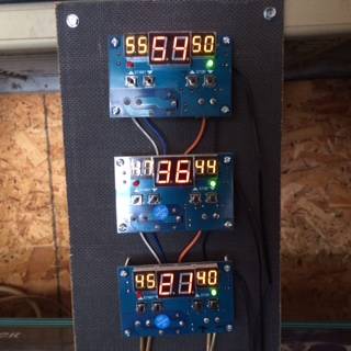
I got those temperature control cards and finally got around to hooking them up. Got 3 but only have the 2 in use so far.

The top unit is hooked up to the heatsink. Just tucked the sensor into the fins.
The middle unit sensor is on the first coil near the stock thermal switch. Loosened the center bolt on the coil and tucked it between plate and rubber
So top temp reading is heatsink and middle is first coil with third unit just reading ambient. (might later have it sense my third coil temp as no switch on that one)
The larger middle reading on each unit is sensor temperature, with the left number the high setpoint or kickin point and the right number is the kickout. Buttons below each for adjusting settings. Easy
Good thing its easy, as the directions were a bit cryptic;


Anyway, just paralleled the two control unit contacts together and then paralleled to the pins of the thermal switch on the first coil or to the toggle switch if you have one installed, whatever is easier. That way all the stock fan controls still operate (hopefully) but now these adjustable controls ensure main fan operation when its needed, without having to change or modify the fans themselves. You could, of course have one card operate the main fan and another run the second fan but I went with simple and easy
I won't be sure of setpoints until I get some hot summer days for real testing but so far so good
Power for the cards is 12 or 24vdc. Since this is all for testing, I just have wires hanging out of the case. When its time for more permanent hookup, easy enough to route wires thru the endplate or notch the clamshell
Sorry about picture quality. Had trouble getting the lighted numbers to show up. As a photographer, I make a good electrician